Building the PMR-7 Twin Cylinder Steam Engine
A friend in Sweden asked if I would build this casting kit for him. I did it some time back, but am
just now getting all the pages put together properly for showing the build.
The engine is a casting kit from the PM Research company in the United States. It's a twin cylinder
double acting mill engine with 1/2" bores and 3/4" strokes.
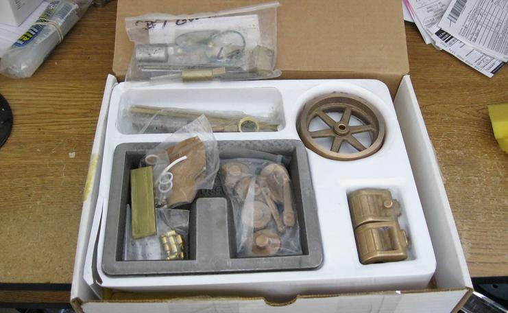
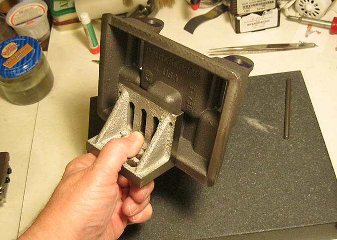
This is the casting kit. PMR makes a top quality product, and the cast pieces here are some
of the best I've come across where the material is concerned. No hard spots in the cast iron,
and no large voids. Slightly pebbly maybe, but they're sand castings after all.
My friend, (Phil) had done some work on the base, along with some work on the flywheel and
cross head tops. After he got into it a little bit, he decided all the American tooling he would need
to buy to get the work done would be kind of hard to come by in Sweden, so he sent it my way.
Casting kits are deceiving for the person who is doing their first one. They look like they would be
easier than making a good looking engine from bar stock because the basic shape is there. Truth is, when
you are handed a raw casting, it's missing something that is not evident just by looking at it. That thing
is a datum. In other words, they don't have a good flat place or proper hole in them to help you in making
the measurement for that first critical cut. You have to sus it out, and if you've not done one
before, it can be a puzzle.
First, I broke out my Chinese tombstone. That's a cheap surface place for those not in on the joke. ;)
I ran around the piece a few times to see if anything was badly off (nothing was), and to get an idea for
the first cut.
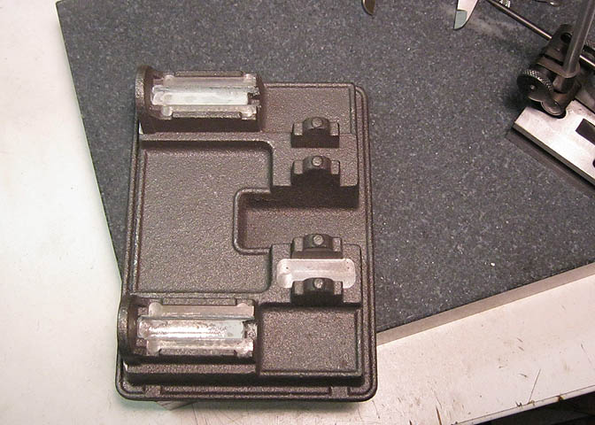
I decided the best place to start was the spotfaces on the main bearings.
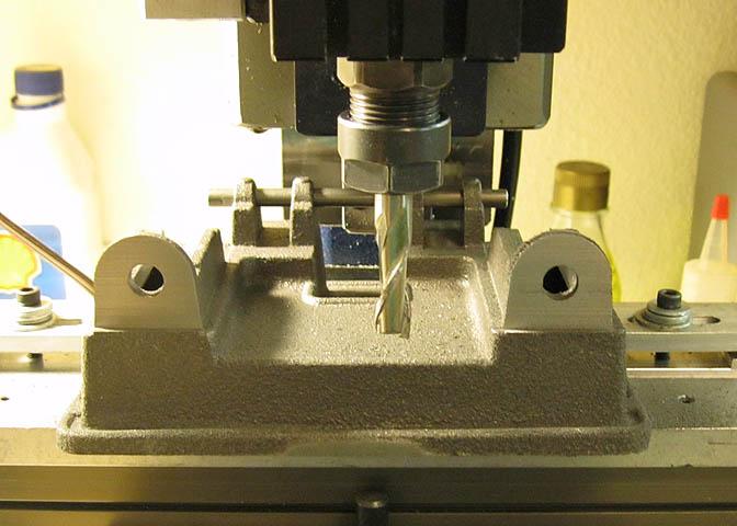
Getting things clamped up on the mill.
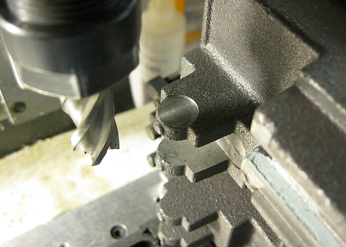
Then, the first spot face is cut with a 1/2" end mill.
And while I'm here, a spot with a center drill. That spot will be a reference for a lot of stuff
down the road. It is what will be the centerline of the crankshaft, and from the crankshaft, I'll lay off
for most all the other features that need to be milled into the base; The distance from crank to rear of
cylinder, the position of the piston centerline, the crosshead ways, and etc., all come off that point.
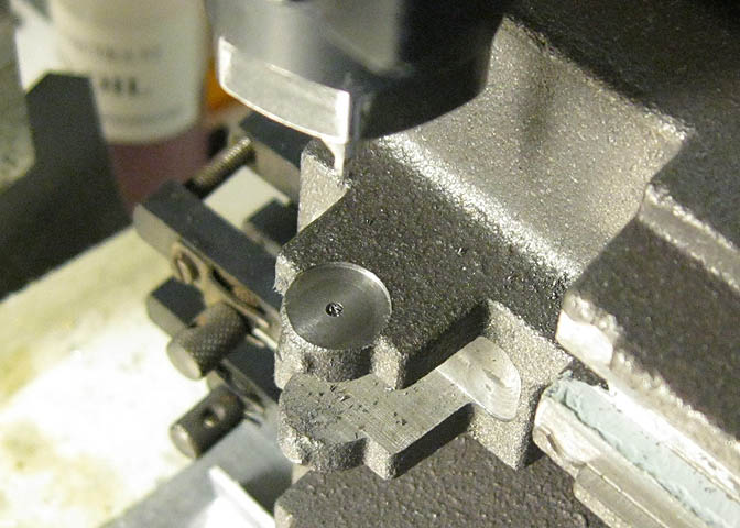
After that first spotface, the setup is broken down and done all over again for the second spotface on the
opposite main bearing.
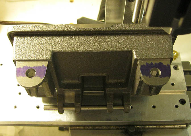
If you look back to the second pic, you'll see some greenish/blue stuff on the crosshead ways. Phil thought
he had made a mistake milling that area out, so put some filler in them which would have been painted over
later. It so happens he hadn't done a boo-boo in the first place, so out with it, and a little more material
removal down inside the ways.
Next thing I want to do is drill through the four main bearing stands for the crank. This can be done on the
lathe by mounting the casting to the lathe carriage, and boring them between centers. That is called align
boring, and would produce the best possible bore. However, it's a tricky proposition when the bore is so small,
at 1/4". I decided to go the next acceptable route, which I'll show here.
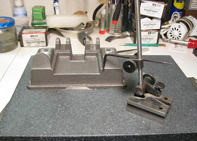
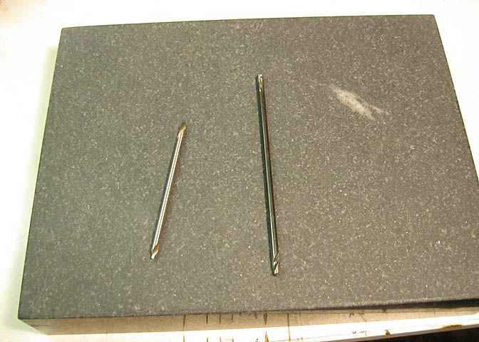
The pic above shows my long center drill and an extra long drill bit being check for straightness on the
surface plate. They have to be good and straight for this to work with good results.
Now, again the base is mounted up on the mill, and that spot I made during the spotfacing operation is found
and the piece is centered under the spindle.
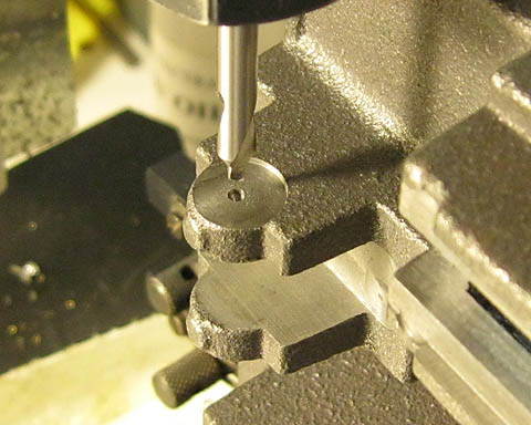
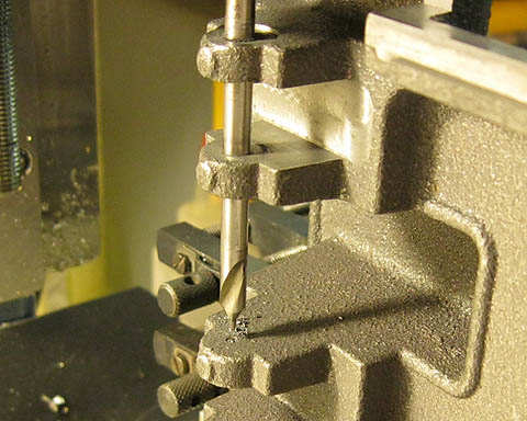
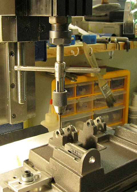
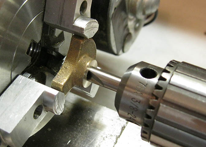
This pic is showing the second step in the operation. The first hole has been drilled with a regular drill bit.
Then the center drill is run down through the first hole to spot drill the second one in line. This way, the
bearing actually acts as a pilot, or guide for the spot drill.
Then the second hole is drilled with a regular drill bit. At this point, these holes are being drilled undersized,
and later will drilled out further and reamed.
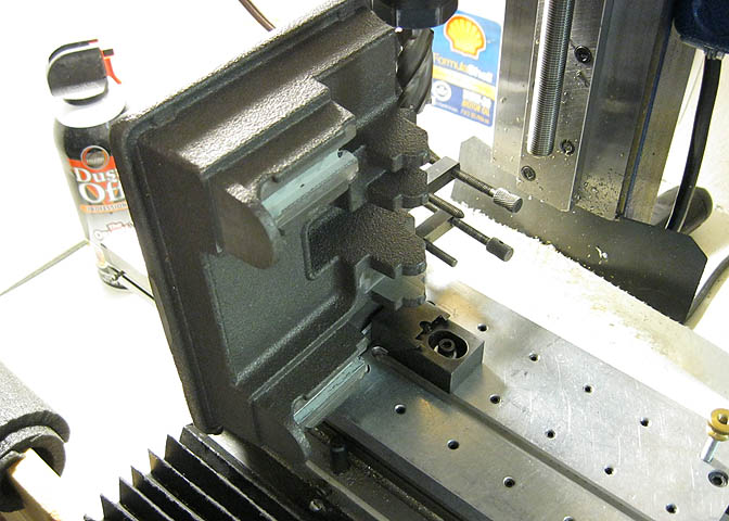
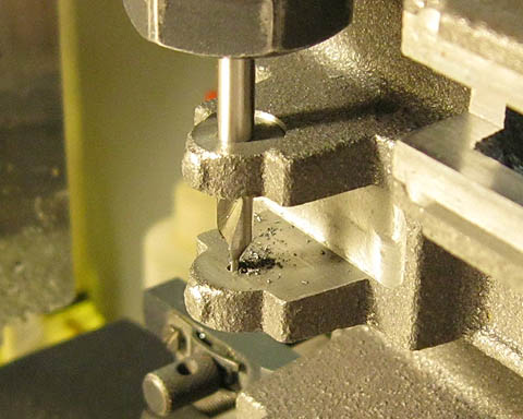
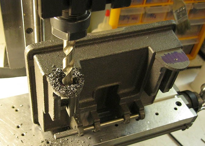
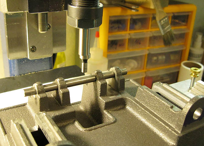
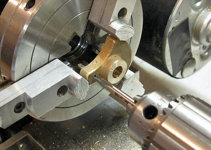
The third bearing is spotted same as the first two. You can see well in this pic how the bearings themselves
guide the spot drill to the proper point for the next hole.
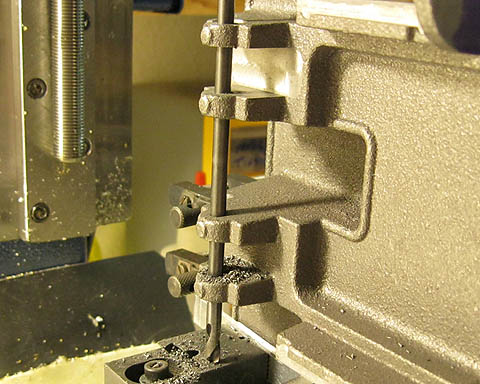
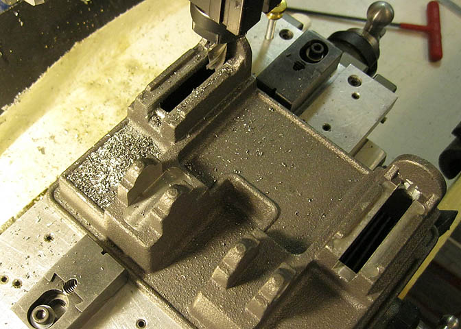
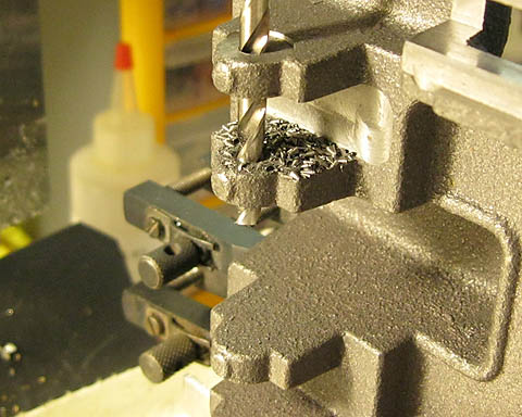
Here you can see the four bearing holes at the last step in this process using the extra long drill bit.
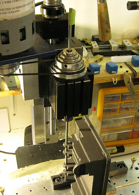
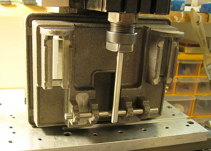
To check my work, I've taken a longish piece of 3/16" drill rod and put it down through the mill spindle.
If they were much off at all, the end of the drill rod sticking up through the spindle would tell the tale
and be easy to see, since it would be off center in the mill spindle.
Since I drilled all these holes undersized at this point, if there had been an error, I would have enough
meat left in the bearings to correct it. As it is, no correction is necessary.
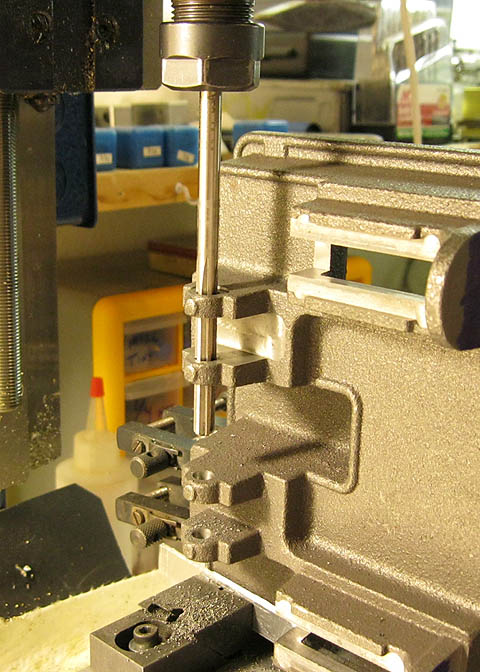
Once I'm satisfied the holes are straight, a long drill bit of 15/64" diameter is run through the holes to
open them up for reaming. Then a 1/4" reamer is run through the holes to clean them up to size.
Now that I have a datum in the form of the bored crankshaft bearing holes, I can put the crankshaft through
them and use it to lay off for the holes that will be the centerline of the pistons.
A piece of very straight drill rod in the mill spindle is used for this, and carefully touching off one side
of the crankshaft, I can then move the mill table to locate the holes for the piston centerlines on top of
the piece.
These are center drilled, step drilled, then bored to the proper diameter.
The finished holes.
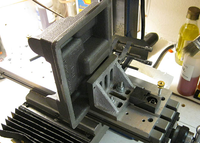
You may (or may not) wonder how I mounted the piece to the mill table. After checking that the base was
flat enough for the needed work, I used some shims to square the base piece on my surface plate, then attached
an angle plate using a few well placed drops of super glue. When I have no further use for the angle plate
on the base, gentle heating with a propane torch will release the glue, and the residue cleaned up with acetone.
When doing something like this, in heating a work piece to release the glue you must take care that you don't
get it hot enough to burn the glue. Super glue is cyanide based, and you do not want to heat the glue enough
that it will turn to a vapor.
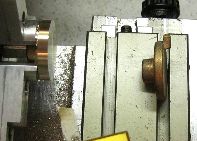
Next pieces to be done are the inboard cylinder heads. These have to be finished before I can drill the holes
in the base piece that will be used to attach the cylinders.
The pieces are bronze castings. After a bit of turning on one side to remove the pouring sprue, the piece is
flipped in the chuck to work on the other side.
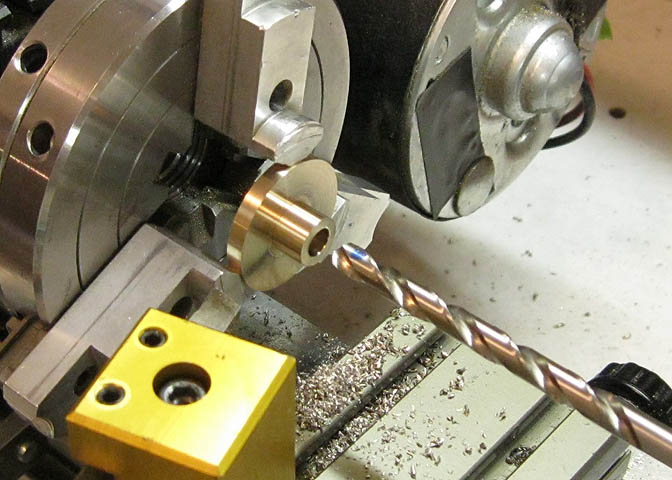
The castings are cleaned up with a tool bit ground for brass, then drilled in preparation for tapping. The
hole that has just been drilled will eventually take the packing gland for the piston rods.
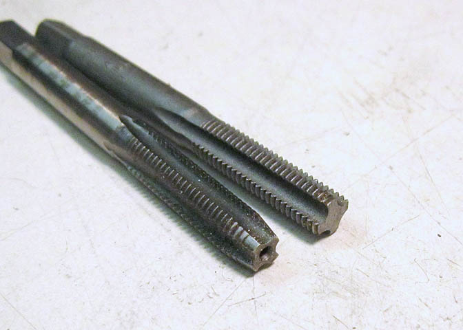
The hole just drilled needs to be threaded all the way to the bottom. The two taps in the pic show a plug tap
and a bottom tap. The plug tap will be run into the hole until it bottoms out, then the bottoming tap will
be run in to clean up the threads to the bottom of the hole.
A full set of taps for one sized hole usually has three taps. The two shown above, and also, a taper tap. The
taper tap looks something like the plug tap, but has a more tapered point. That one is not needed for a hole
like the one threaded here, but for holes in thin metal, or for through holes, a taper tap is easiest to use
because it cuts the threads more gradually then the other two. A taper tap also helps in getting threads
started straight when you have to do your tapping by hand, with a tap wrench.
The names I've given for these taps are correct in the States. I think the terms are slightly different in
the U.K., and maybe in other parts of the world.
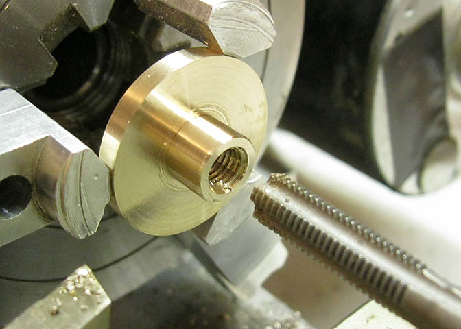
After starting the threads with the plug, the bottom tap is run down until it stops.
Now, the distance from the centerline of the crank to the face of the cylinder mounts needs to be set. This is
where having the crankshaft bearings bored helps to get quite precise measurements for other features on the piece.
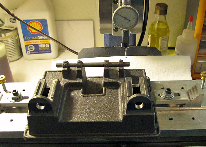
The base is clamped down lightly and the crank put through the bearings. Then using a test indicator along the
back side of the crankshaft, the piece can be squared to the spindle of the milling machine. The indicator is
run down to get a reading from both ends of the crank, and using a brass hammer, the base is lightly tapped
until it is true to the milling machine. Once that is done, the clamps are tightened down.
The back side of the crank is "located" using an edge finder. Once I have the center of the crankshaft
I can easily find where other features on the base are to be located.
Here, the cylinder mounts have been cleaned up with an end mill, and the distance from the mounts to the centerline
of the crankshaft is set. When you do things this way, you also have to keep the diameter of the end mill in mind.
While I have the piece squared up on the mill, might as well tap the holes in the bearings for the oil cups.
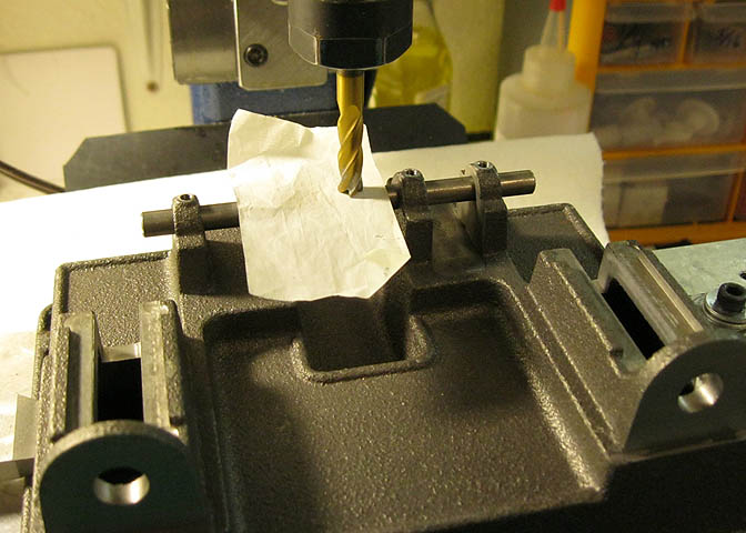
I have to do some milling on the crosshead ways, too. In this pic, a piece of cigarette paper is being used to
"touch off" from the top of the crankshaft. I know how thick the paper is, so an end mill is run down until it
just starts to grab the paper as I move the paper around a bit. The mill is not running while doing this.
Once I have the end mill set to zero on the Z axis, I can crank it down half the diameter of the crankshaft, and
again, have centerline, this time in a vertical orientation though. From there, it can be cranked down to the
dimension called out on the print, and the crosshead ways milled out.
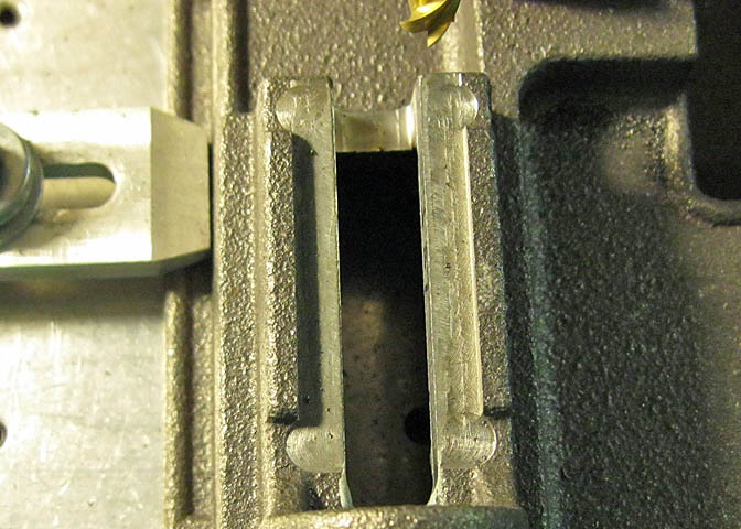
A start had already been made on these when it came to me, and all I need to do here is cleanup
about .025" to hit dimension.
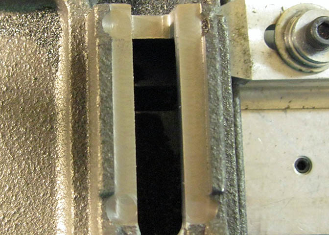
A bit of milling, and they are done.
You can see a difference in the two pics regarding finish. On things like this, the better the finish, the better
the parts will run together. I don't mean the way it was would stop the engine from running. It would have
meant the engine would have to "break-in" longer.
If you have trouble getting a good finish, it could be for a few different reasons. Usually it's associated with
a dull tool, or a tool not well suited for the purpose. That would be the first thing to check, along with making
sure your machine is well in trim.
Finish problems can also be caused by running the tool too slow, or too fast. Another thing that can cause it, and
one that may not come readily to mind is "re-cuts". Re-cuts are pieces of swarf that have already been removed by
the tool, and are then picked up by the mill flutes and forced back through the cut again as the end mill progresses.
Those little things can leave a lot of machining marks.
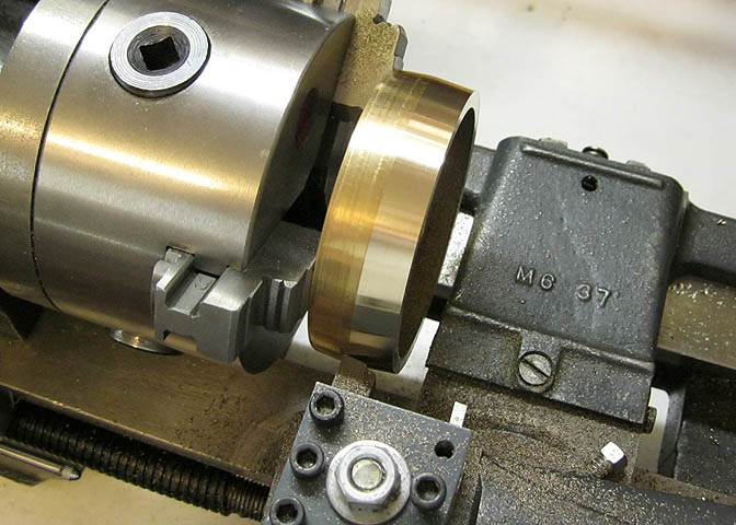
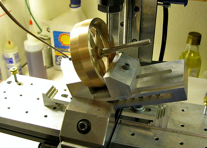
For the next piece, I want to clean up the flywheel a little.
This is a preliminary cut, and it gives me kind of a guide when I finish up the crown on the flywheel later.
While it's in the chuck, the outer rim is also skim cut.
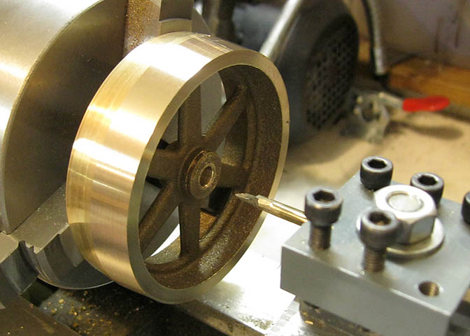
While the piece is still in the same setup, the center hole is bored. This hole will be "the dictator" for
all cuts coming up, and all future cuts on the flywheel will be made with this hole as the center of the universe.
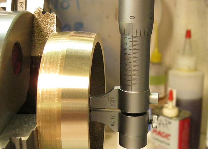
Just checking. .250" plus a sniff, so the crankshaft will be able to go in, but not be sloppy.
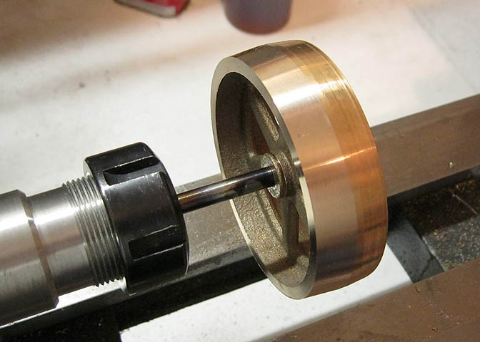
Now I'll use a piece of drill rod as an arbor to finish up the cutting on this piece. Drill rod is a polished and
ground tool steel in an annealed state. It's very straight and smooth (if you buy the good stuff). Perfect for
a nice one use arbor, since it's not too expensive.
In the pic above, I've used blue Loctite to adhere the flywheel bore to the piece of drill rod. I went out for a
haircut and while I was away, it cured well, so I can get to work.
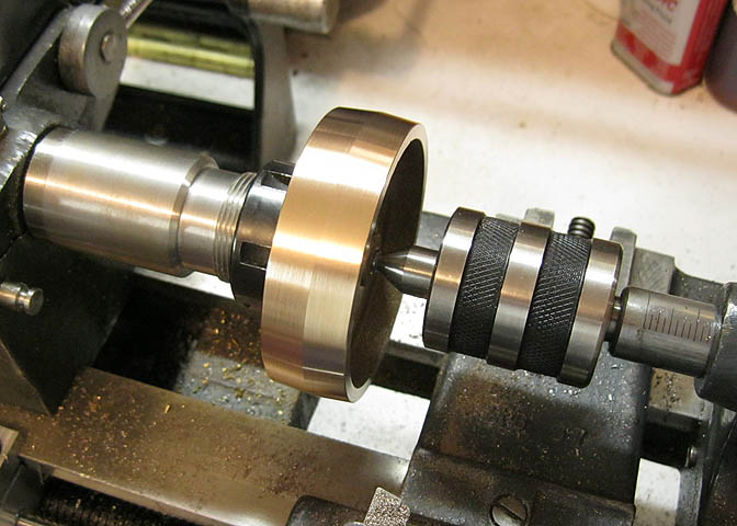
Now the rod is pushed up into the lathe collet and tightened down. Then a center drill is used to drill a 60 deg
tapered hole in the end of the drill rod, and a live center is used to support the end of the rod.
Now I can finish up all the cutting on this piece and know that all the cuts I make will be right off the centerline
of the flywheel bore.
The first angle on the flywheel crown is cut again by setting the compound slide over 5 degrees. The cut is taken
well past the center of the flywheel rim so when I make the second angle on the rim, the cuts in the middle of the
rim will overlap, ending up with the crown right in the middle, where it should be.
The pic above shows all this stuff already done.
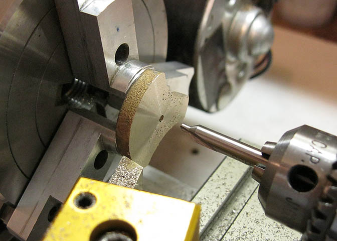
Last thing to do here is to drill and tap the set screw hole. To get the hole dead center in the flywheel hub
I've used a piece of rod in the hole, and touched off one side of it with the center drill. Crank over the
mill table and drill and tap.
Some work on the crank throws now.
The throw casting(s) are first chucked up on the boss and the large flat faced off. Then it's center drilled,
drilled and reamed to take the crankshaft.
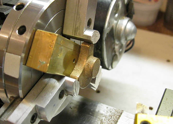
Next the piece is turned over and pushed up against a piece of flat stock as the jaws are tightened. This
will keep the flat on the big end parallel with the facing cut I'll make on the boss.
This step is out of the regular order of things. The pic is a staged shot just to show the use of the piece
of square stock.
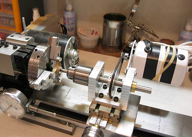
Next, I need to drill the crank throw for the screw that will hold the piston rod. The setup in the above shot
shows my auxiliary spindle for this lathe to help illustrate what is going on here.
I'm using a center drill here that is the same size as the bore in the crank throw. By cranking the cross slide
back and forth until the center drill slips into the bore, I can find the center of the hole, which will then
let me crank the cross slide back toward me for the distance needed for proper spacing between the crank throw
bore and the bore that will be on the big end of the connecting rod.
Once it's cranked over the correct amount, the hole is center drilled, drilled, and tapped for the rod screw, and
the lathe work on this piece is done.
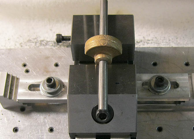
Last operation is to tap the set screw holes in the crank throw bosses. A piece of rod is run through the bores
and the whole shebang is laid across the top of the mil vise. When the vise is tightened down, the rod will keep
the pieces at the same level and square to the table on the mill. Then the rod can be used to locate the mill
spindle directly over the crank throw bores, and the set screw holes are drilled and tapped. (The rod is
removed before the holes are drilled.)
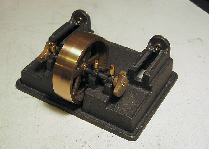
Here's where I ended up for this page.
Go to Part 2
Back to:
Part 1
Part 2
Part 3
Part 4
Part 5
More Taig Lathe & Mill Projects
Copyright 1998-2010 Dean Williams