Building the PMR-7 Twin Cylinder Steam Engine
Part 4
Starting on the cylinders, first thing I check is the rim around the bore to see if the cored hole is well in the
center of the casting. It is, so I can use it as a rough guide when putting the piece in the lathe chuck.
The piece is put in the chuck and the core hole indicated just to make sure I haven't got the piece cocked to one
side in the chuck. You can't indicate a thing like this to run at zero of course, but it can be checked for
"ballpark", which is about all you can expect for something that doesn't have a truly round surface anywhere on it.
One end is faced off to begin.
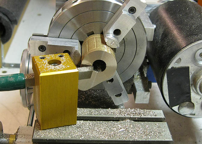
After facing, the cored hole is bored to size. This is the end that will mount against the cast iron base.
Facing and boring are done without disturbing the piece in the chuck, so the flat end and the bored hole
will be perpendicular. That is a must if you want to have the piston running true with the bore when
the engine is assembled.
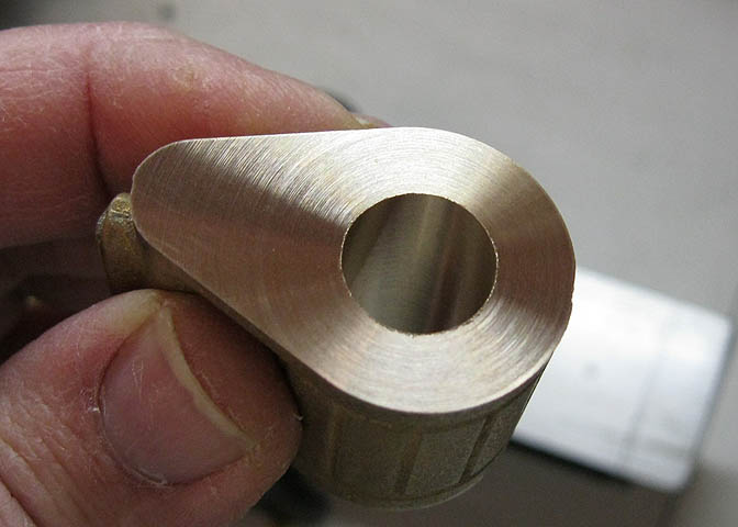
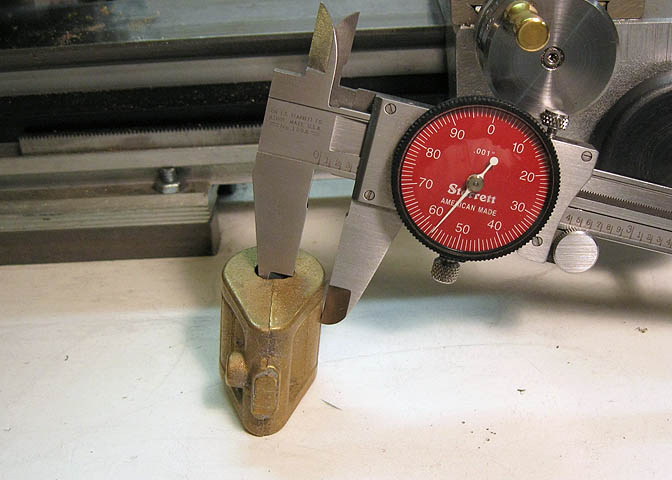
Here is the cylinder bore done. I worked for a very smooth finish on the inside.
I also worked to a very close tolerance, according to the print. To check my work a .500" ground gauge
pin is put into the bore. It slides in with little resistance, but will not fall out when the cylinder bore is held
in a vertical position. 'Bout the best I can do.
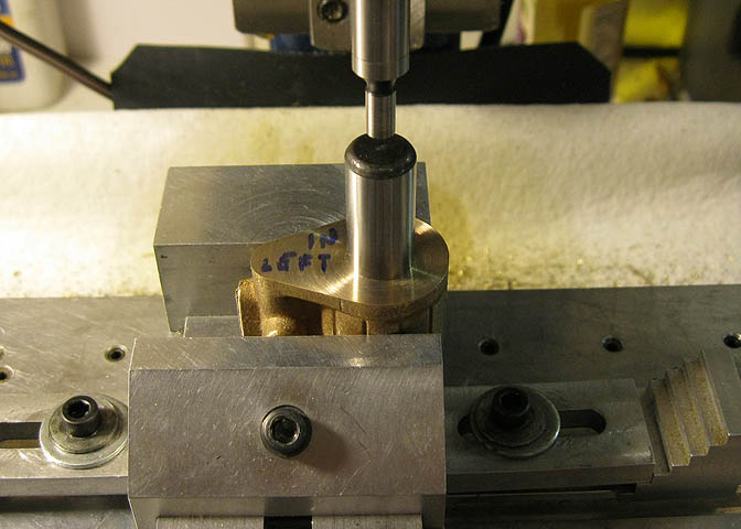
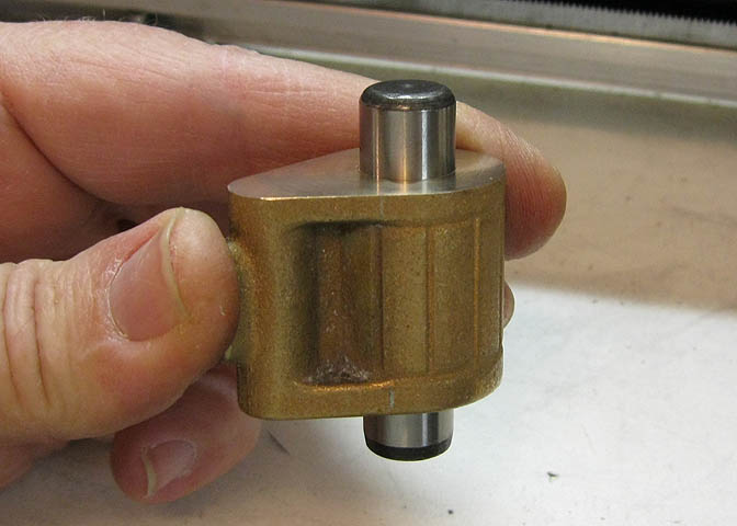
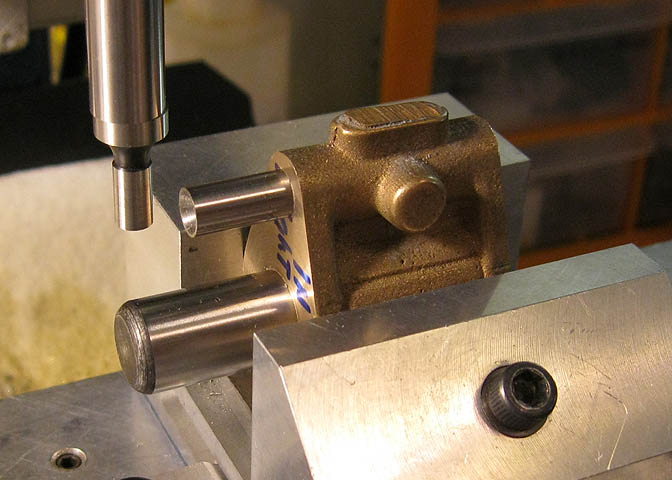
To setup for boring the valve chest, the cylinder is put in the vise and a gauge pin put in the piston bore.
The center of the bore is found using the edge finder, then the mill table is cranked over using the dial
grads to locate the valve bore.
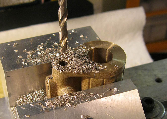
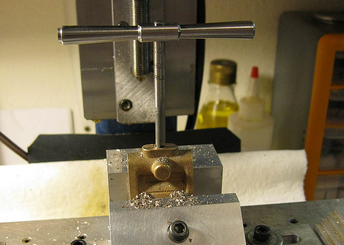
The valve bore is two diameters. One that fits the valve, and one small part on the end that is threaded for
the exhaust pipe. The smaller diameter is drilled all the way through first, then the larger is drilled to depth,
and reamed to hit finished dimension.
When the valve bore is done, the piece is lain on its side, and two pins are used to locate the top
center of the steam inlet for the valve chest.
Once the piece is lined up, the dial graduations are used again to locate the hole for the steam inlet
and the two passages needed that will connect the steam chest to the cylinder steam inlets.
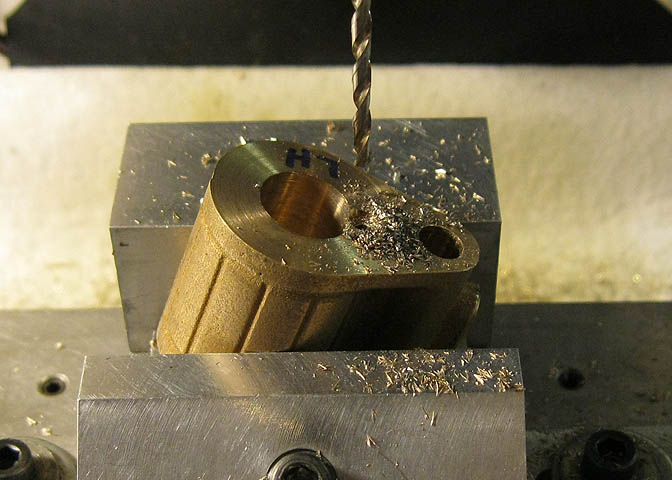
To drill the cylinder passage the cylinder was set up in the vise using an adjustable protractor. Then the inlets
were spot faced and drilled down to meet the passage from the valve chest. This is always a fun part, waiting
for the drill that's boring the passage to meet up with the other passage that you can't see.
All that's left to do is drill the holes for mounting and for the outboard heads.
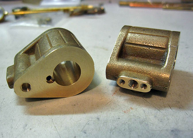
The threaded hole between the two smaller holes is the steam inlet. This is part of the deviation
from the prints that the owner and I agreed on for connecting the governor butterfly valve that will
be shown later. It makes a somewhat cleaner installation of the governor, which, as was mentioned
earlier, is not a part of the factory casting kit.
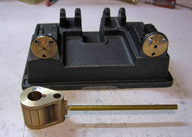
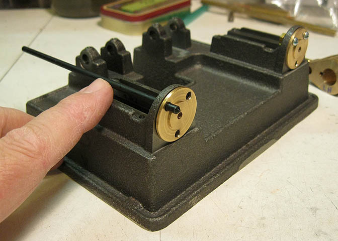
Time to drill and tap the mounting holes in the cylinders. To get them square, I started
by putting a long piece of pipe into the steam inlet.
Then holding the cylinder tightly against the cylinder support, the piece of pipe is lined up
with the piston rod on the adjacent side.
A transfer punch is then used to mark for the holes that go in the back of the cylinder.
These punches come in a set, and each one is the size of a certain drill bit. If you drilled 9/32" holes in a
pattern and need to transfer the pattern to another piece, pick the transfer punch that is 9/32" and it will
fit exactly in your previously drilled holes, putting center spots where you want to drill your new holes.
The other end of the cylinders were drilled and tapped for the heads, and then time
for another fit up to see how things get along.
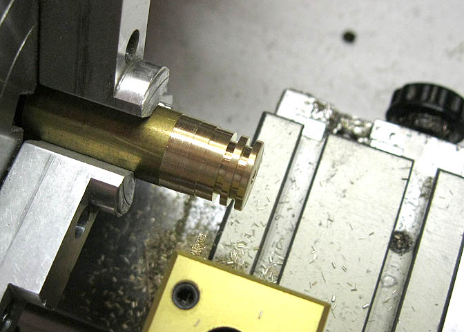
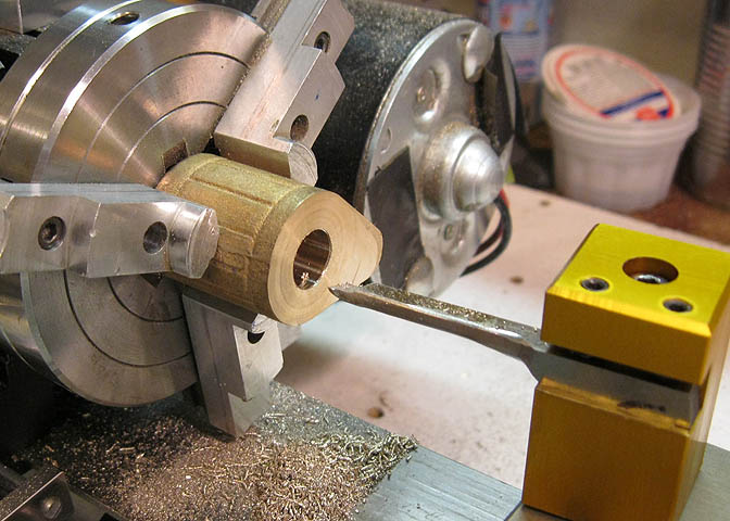
To start on the pistons a piece of brass stock is turned down to cylinder bore diameter -.001". Then I
ground up a small cutter .050" wide to cut the ring grooves.
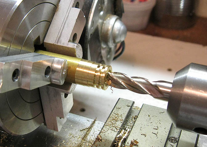
The end gets a small hole drilled through to take the con-rod, and then the end has to be counter bored
so the nut that holds the con-rod to the piston sits down inside. I used an end mill for this, since the
bottom of the bore needs to be flat.
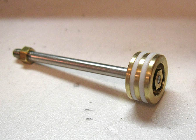
This is how it goes together.
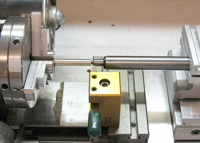
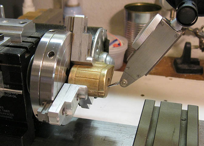
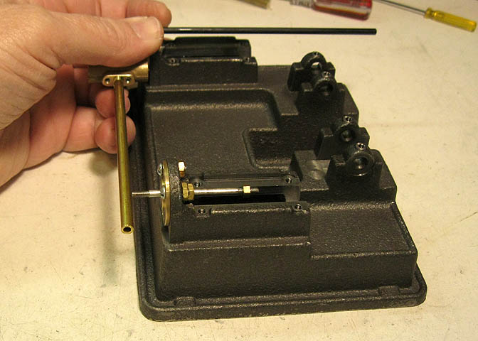
Next, the valves. Similar to the pistons really. Since they are a bit long, and the material is small diameter,
a live center is used to hold the free end. A piece this slender and sticking out this far will chatter if the
free end is not supported.
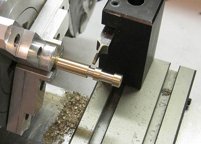
The steam passage diameters are turned using the parting tool. The live center was used for these cuts too, but
has been removed in this pic to prepare for the next step, which is drilling the ends of the valves.
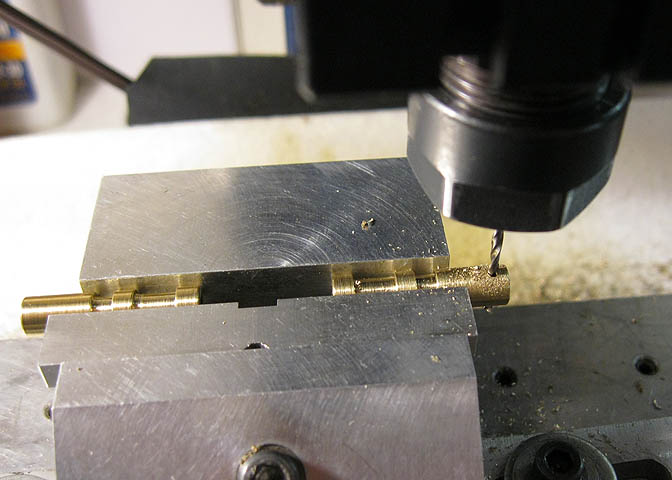
Then the valves are put in the mill vise for drilling the exhaust port and clevis pin hole. By putting them both
in the vise at one time, once the center is found over the top of one valve I can start at one end and drill the
four holes right down the line.
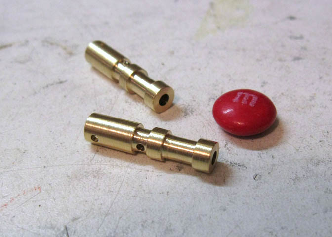
That's them, done.
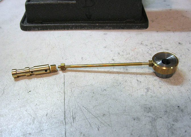
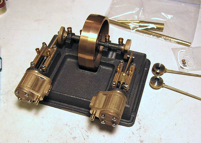
This shows how they go together with the rest of the eccentric and rod. The clevis goes into the end of the
valve and is pinned. Then the end of the clevis is screwed onto the rod.
The rods have to be bent yet, and then a bunch of fine tuning as the engine is assembled. The engine parts
are mainly done at this point. The governor is next, along with pictures of the complete engine.
Go to Part 5
Back to:
Part 1
Part 2
Part 3
Part 4
Part 5
More Taig Lathe & Mill Projects
Copyright 1998-2010 Dean Williams