Building the PMR-7 Twin Cylinder Steam Engine
Part 2
Today I'll do the rods and their big end bushings. The rods are castings, and have to be cleaned up with a file
to remove flash. One of them is a little off kilter from the mold halves being mis-aligned when the castings
were poured.
Also, the sprues have to be filed off. This is where the molten metal was poured into the mold.
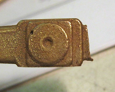
They get put in the mill vise and an end mill is run over the bosses on each end to provide a good flat surface.
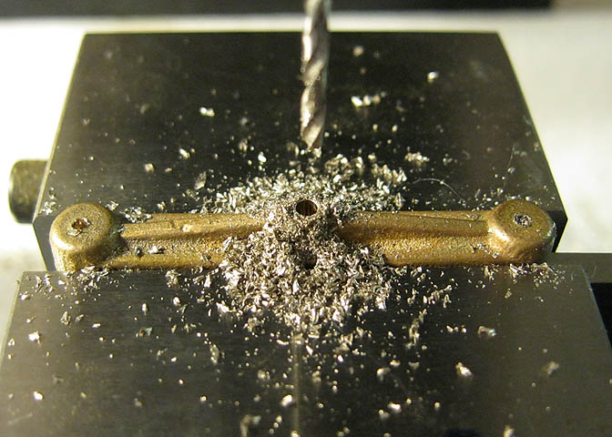
The small end is drilled in the casting dimple, and from that hole the mill table is cranked over a known amount
to locate the hole in the big end of the rod.
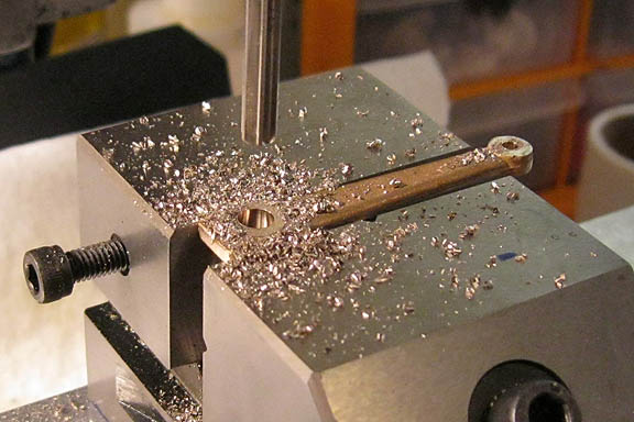
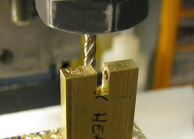
The big end is not drilled in the casting dimple. The prints call out a three decimal figure for the location of
this hole, and no way will the casting be that accurate. A drill is not used to start the hole here, since
it would want to slip into the dimple no matter how hard you might try to get it to drill in a different place.
That is the reason for starting this hole with an end mill. They will not flex (practically speaking), and I can
get this hole exactly where I want it.
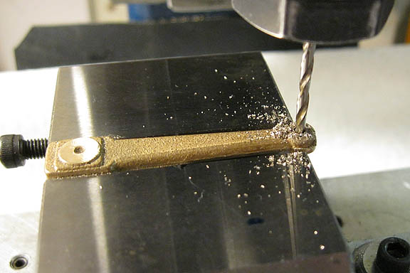
The dimension between hole centers is to be 1.656". When prints call out a dimension like that, it means they
really want you to pay attention. Most proper prints will have a tolerance table on them somewhere. For this PMR,
when they have three figures behind a decimal point, it means they want the dimension held to within +/- .005".
The end mill will do that. A drill bit won't.
After the end mill has started the hole, it can then be drilled almost to size, and the hole then finished with a reamer.
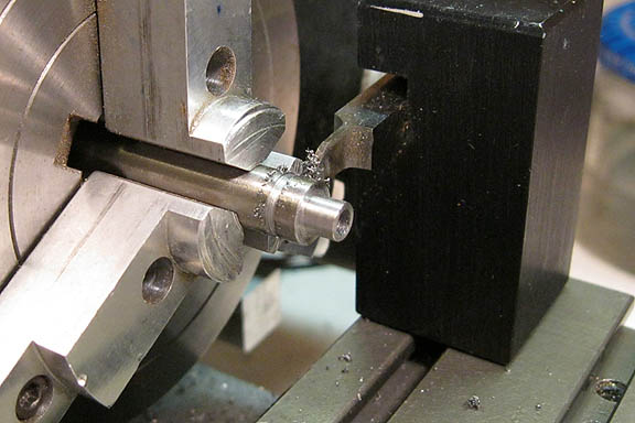
With the rods finished, I turn to the rod bearing. This is steel, and for the most part just a little round
thing with two diameters. A hole is drilled through, and then the thing is parted off.
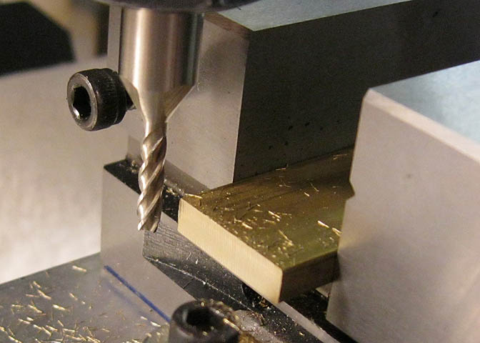
This piece of brass will be the crosshead slippers. First step is to square both ends with an end mill.
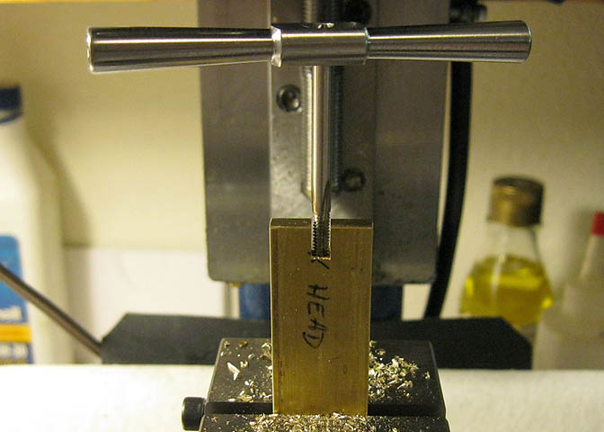
A cross hole needs to be drilled for the rod pin. The piece is put in the vise and the work stop on the vise is
tightened down against it. The hole is drilled, then the piece flipped end for end and a similar hole drilled
in the opposite end of the piece. This way I can get one crosshead off each end.
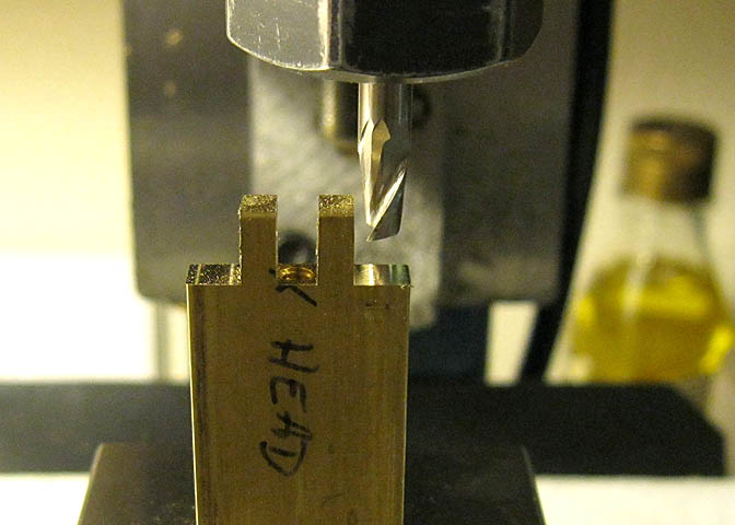
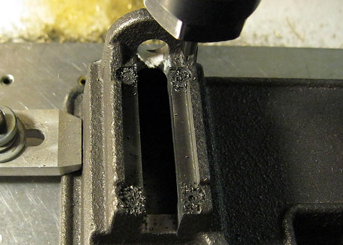
The piece is stood on end and the slot for the rod end milled in.
Then, while the piece is centered from the last milling step, a hole is drilled and tapped in the end for the
piston rod.
The remaining material removal is finished up.
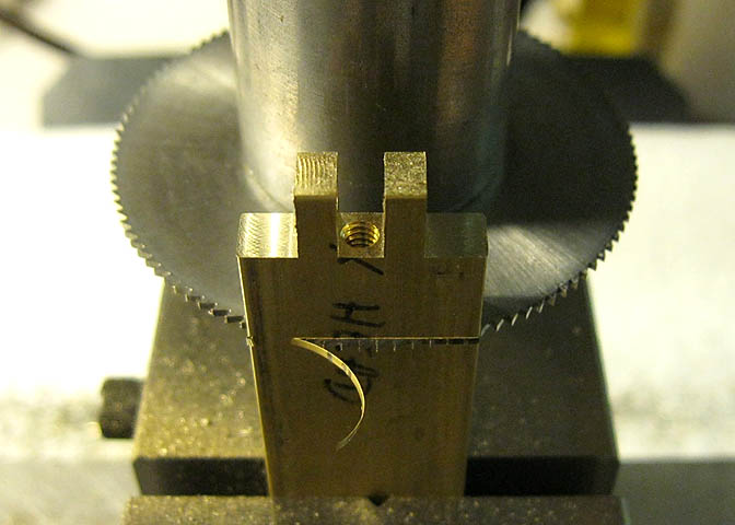
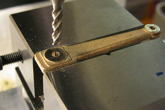
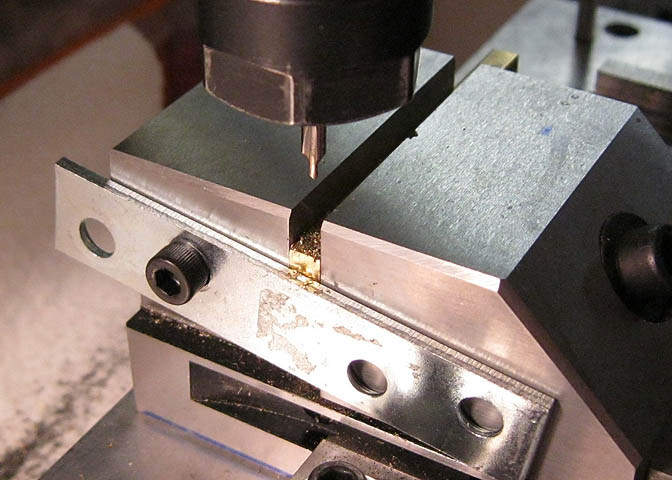
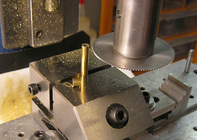
Finally a slitting saw is used to cut the piece off to length. I took a number of passes at .025" each. A slitting
saw this thin would not make the complete cut in one pass. It would get hot, and possibly break. A good chance of
sticking in the cut too, if too much material is taken at once.
In the shot above you can see the last cut being made. I stopped here to put a thin piece of wire through the
hole in the end of the piece and held it from above so the piece would come off cleanly.
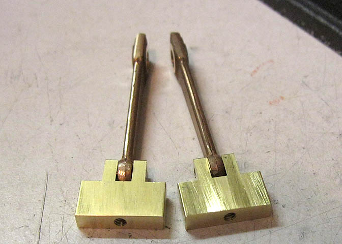
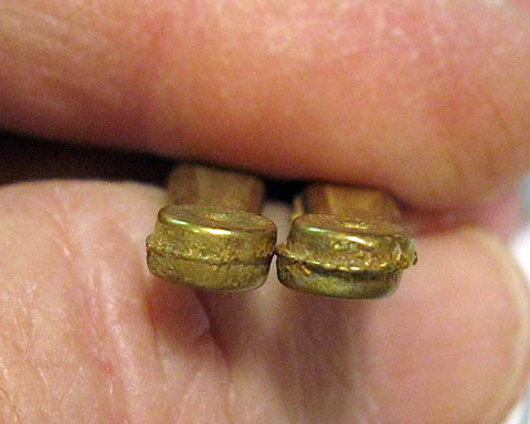
These are the finished items shown with their con-rods.
Time for the crosshead caps. Just drilling and tapping here. Once I have the piece centered and spot the first hole
it's a matter of using the table X axis dial to put the holes in the correct place.
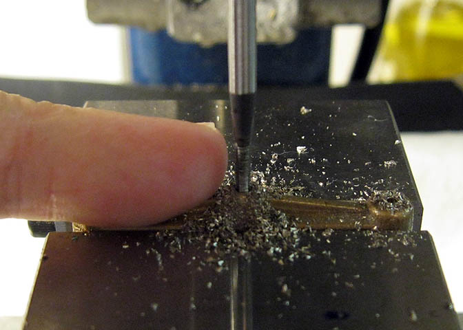
The tiny center boss is tapped for an oil cup on each of the four castings. That's my little finger next to the
#2-56 tap. Main thing about using small taps is to keep them straight, drill the proper sized tap hole, and don't
put any side pressure on the tap. They break very easily.
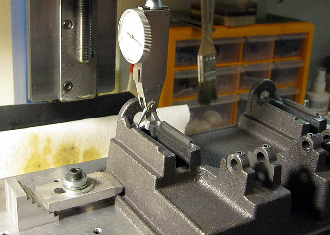
Now the base casting is mounted on the mill table and dialed in with a dial test indicator.
Once I have a straight line on the side of the cross head flange, (square to the machine), the first hole can be located
off the front of the cylinder support and one of the flanges. Then the dials can be used to locate all the holes.
They are drilled and tapped for the crosshead cap screws.
Eight spacers for the caps have to be made. I used a piece of 3/16" model pipe for this, and drilled out the inside
to take the needed screws. I was going to part these off in the lathe, but decided a slitting saw would be faster,
as it leaves less of a burr, (but there will still be some).
The top of the pipe is cut off first to give a good flat end for a start, then the spindle is cranked down for the
length of the needed piece, plus the thickness of the slitting saw. Then, cut cut cut.
For folks who might want to use one of these tools, but have no experience with one yet, there are a few things
that may help you get along with it;
Generally, you want to run these slow. It's not like a wood saw, and won't do well with high speeds. The outer
surface speed of the teeth is increased over the indicated speed of the milling machine because of the diameter
of the tool. Going too fast will get the saw hot, which will shorten its life.
These are high speed steel, and will not take much side pressure before they break. Be careful not to change the
Z setting on the machine while you are cutting.
Take a number of shallow cuts rather than one deep one. A deep cut will often cause the saw to grab the work.
Obviously, keep your tender body away from the teeth. You won't believe how fast one of these will lay you open.
All HSS tooling is sharp by nature. The diameter of a slitting saw means you have a bigger chance of getting close
to it while you're working. Be safe.
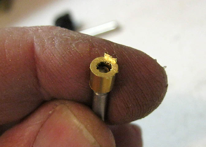
The pieces all had to be cleaned up after cutting. They are too small to hold between fingers while filing off the
burrs, so I made a tool to hold them. It's a piece of rod with one end turned down to fit the ID of the piece so
I can clean them up easily. You can just barely see the small shoulder that catches on the little brass piece.
Took longer to de-burr than to cut them up.
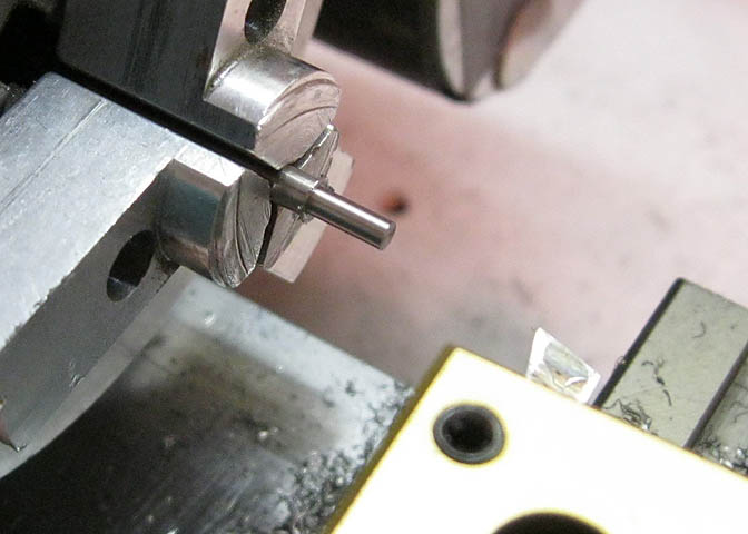
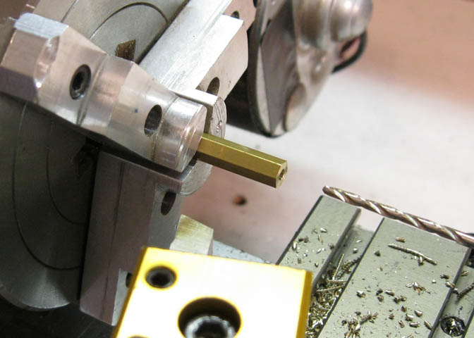
Making the piston rods and the fasteners that will be needed for various parts on the kit.
Above, I'm using a die and die stock to cut threads on what will become one of the piston rods.
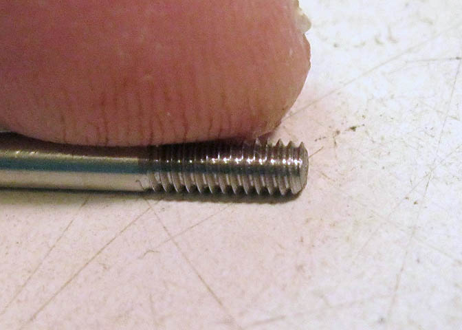
When you cut threads, if you will make a small bevel on the end of the piece using a file, the threads will look
nicer, and they will also start easier when screwing them into other parts. With the lathe running, use the file
to put on a small 45 deg bevel.
Be very careful when using a file on the lathe. It is a proper machining technique, so I'm not telling you to
do anything unusual here. Just be aware of the spinning chuck, and where you put your hands and the file.
ALWAYS use a handle on a file, especially when filing on the lathe.
Run the lathe in the normal rotation, pushing the file away from you. A file is not a saw, and you do not file on the
fore and aft strokes. Only when pushing the file away from you, then lift it slightly to return to your next filing
stroke. That holds true when filing in the lathe or filing flat on a bench.
The other end of the piston rod has a smaller thread, so the rod is cut down to the needed diameter.
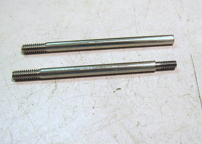
Here's a finished rod, and one that is partially done.
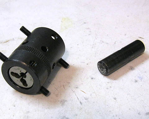
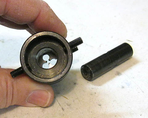
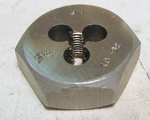
Since there won't be a lot of parts done today, maybe it's a good time to talk a little about tapping and
cutting threads with a die. The thing in the picture above is a die stock. You may have guessed, it holds
your die. This one is made to be used in the lathe tail stock. The smaller diameter rod fits in the the
tail stock chuck, and the large piece slips over it which keeps the die straight, and you can spin the die
with your hands or by using a rod in the holes in its circumference.
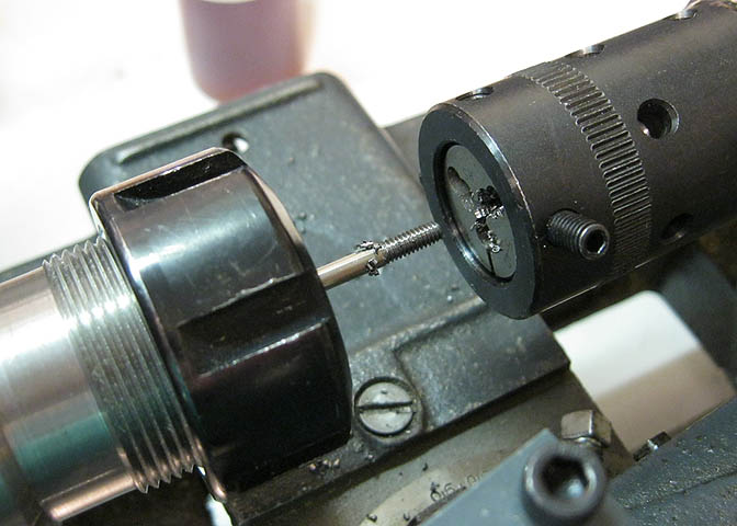
Here's a view from the end.
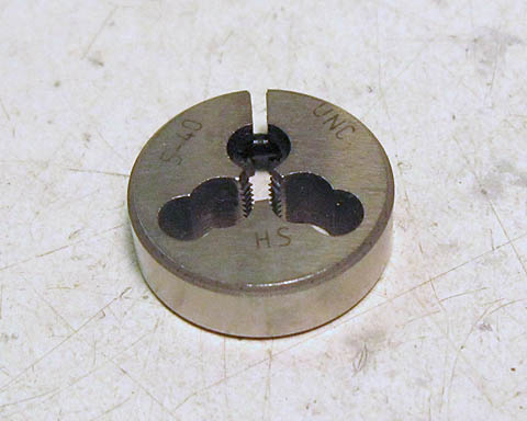
There are a couple of basic types of threading dies. I usually use a split die, like the one in this pic.
The split is there so you can adjust your die to cut a thread that is properly sized. There are probably 10
classes of thread for each thread size, and the class # denotes tolerance and clearance. I won't go into
that. Suffice to say, using an adjustable die is probably the best way to get a properly sized thread.
You can see on the circumference of the die there is a little screw. That can be screwed in, which in turn
spreads the slit in the die to adjust the thread tolerance the die cuts.
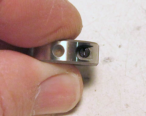
Some split dies don't have this little screw, and the way they are adjusted is by tightening the allen screws
you can see around the OD of the black die stock a few pictures previous.
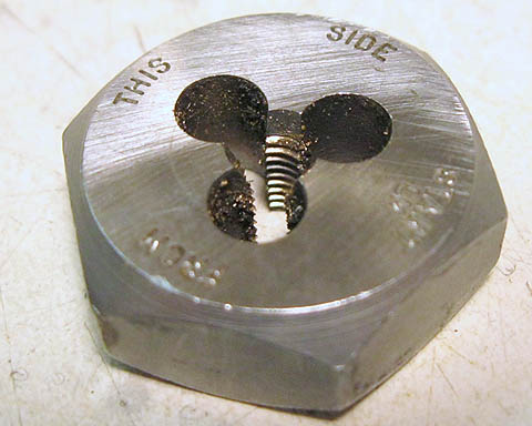
This is another type of die. It's often called a thread chaser, and is usually used for cleaning up existing
threads, although with some effort, it will cut threads too.
In the above pic you can see the end of the threads in the die. Notice they have a rather long taper ground
into them on this side. That is to help guide the piece you are threading into the die. It helps, but it
also keeps you from threading right up to a shoulder.
Flip that die over, and you can see that the threads on this side go right to the edge, so you can finish threads
up close to a corner, as would be needed on some types of step bolts.
You would have a hard time getting a thread started if you went at it from this side. That's why at least one
side of a die will have the threads tapered. Some dies have both sides tapered, which makes them useless for
threading up to a shoulder. I don't know why they do that.
Back to work. I want to make some of the nuts needed for the kit. It's pretty easy with the correct sized hex
stock. First, drill the correct sized tap hole.
Then run the tap into the hole. You do this with the lathe power off, generally. Turn the chuck by hand. There
are cases where you would use the lathe power to tap holes, but that is not for small lathes. They simply turn too
fast to control the tapping process, and you'll likely end up with many broken taps. That's something you really
do not want!
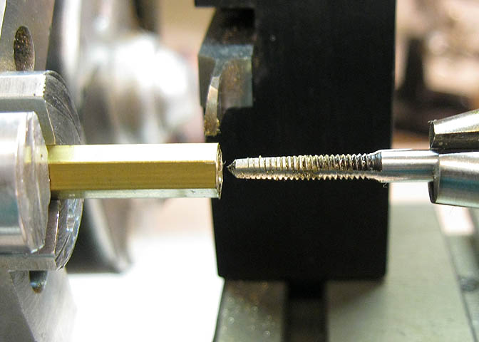
When tapping, if you follow a few rules you will have better success, and fewer broken taps. Start with the proper
tap type. That would be one with a taper on the end, and depending on how steep that taper is, will be called a
taper tap or a plug tap. The third type is called a bottoming tap, and it has threads right on the end of the tap.
That type will be hard to get started in the hole, and that can make for broken taps, again.
Start your tap in the hole and turn it in a couple of threads, then back it out a half turn to break the chip. Then
in one turn, out a half turn, and so on. Every three rotations, pull the tap all the way out of the hole and clean
it off, and blow the chips out of the hole with a puff of air. Watch your eyes. (You're wearing safety glasses, right?)
If you are tapping into a blind hole, this cleaning out step is most important, as letting a bunch of chips accumulate
in the hole will jam the tap, and you'll probably break it. Go easy as you come to the bottom of a hole, and anticipate
the tap bottoming out. You don't want to come upon that point quickly or, again.. broken tap.
You must keep your tap straight in the hole. I has to start on center, and mustn't take any side pressure. That is
the probably the main reason for breaking taps. They simply won't bend at all.
For tapping brass, no cutting fluid is used. For steel or aluminum, you need some kind of lubricant. For steel it's
best to buy a commercial tapping fluid made specifically for tapping. For aluminum, I find either candle wax, kerosene,
or WD-40 work well. It's one of the few things WD-40 actually does well, probably because it's mainly kerosene or
light diesel.
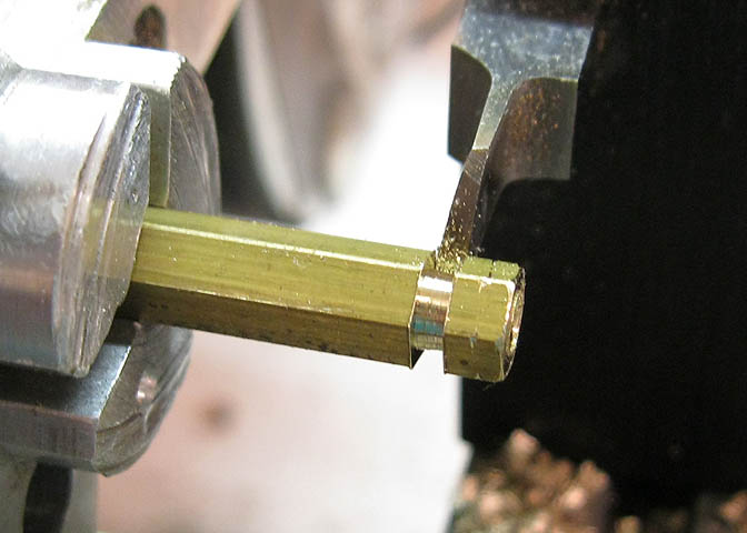
After tapping, the nut is parted off.
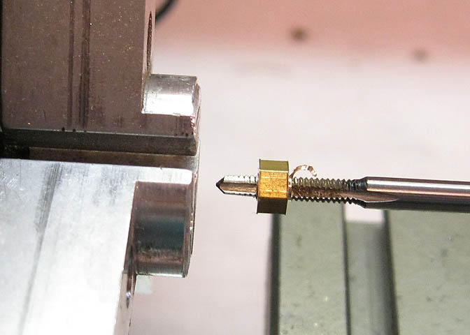
There will usually be a burr left on the nut after parting off. They are too small to hold and file off, so using
a tap or screw to hold the nut, it's put into the chuck with just the end sticking out. Take out the screw or
tap, and clean up the end with a sharp lathe bit. That's it.
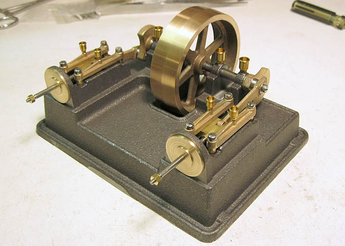
An assembly shot, and stopping point for this page.
Go to Part 3
Back to:
Part 1
Part 2
Part 3
Part 4
Part 5
More Taig Lathe & Mill Projects
Copyright 1998-2011 Dean Williams