Building the PMR-7 Twin Cylinder Steam Engine
Part 3
I'll show a quick few pics here demonstrating how I finish model pipe elbow castings.
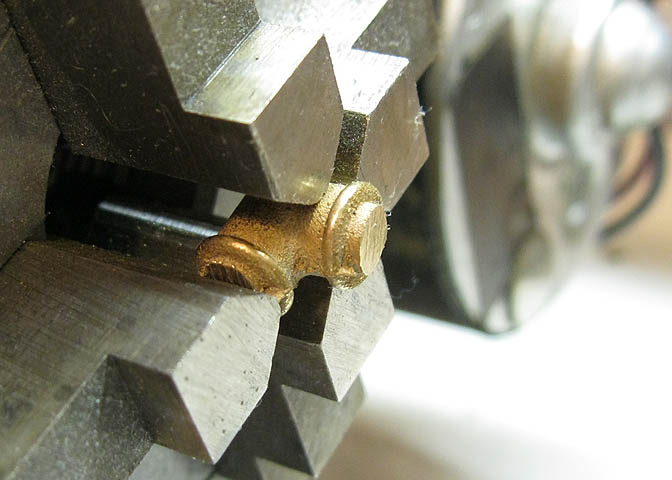
I use a four jaw chuck for these due to their odd shape. Three jaws are snugged against the piece on the parts that
are somewhat round, and the end that is at 90 deg to the lathe axis is left loose for a minute while the piece is
aligned as well as possible. I start just by adjusting it by eye, and adjust the three jaws that are against the roundish
part until the flange appears to be running true. Realize that being a casting, there may not actually be anything
round on it at all. You have to pick your best guess, spinning the chuck 'round by hand until it runs to your satisfaction.
Then the fourth jaw is snugged down, and the piece is faced off.
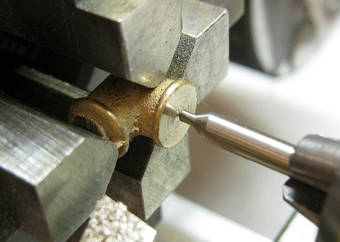
After facing, have a good look at it, and if it appears centered, it probably is. If it looks to be running in an ellipse,
make further adjustments to the jaws, then take another skim off the face. After that, center drill it.
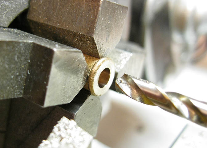
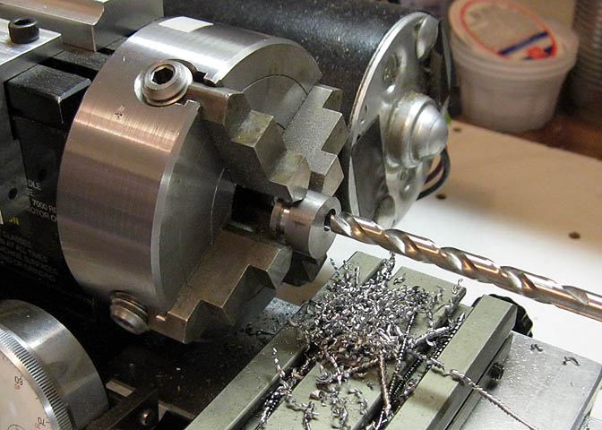
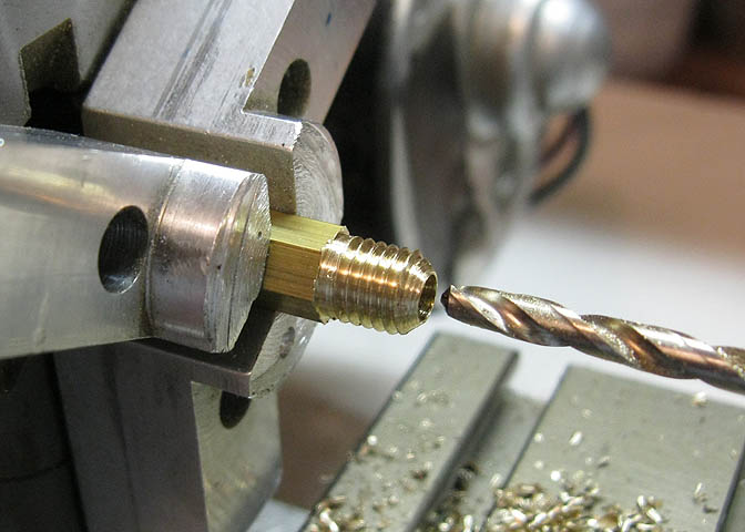
Then the tap hole can be drilled. On this size, which is 3/16" model pipe, and 40 tpi straight pipe thread, the depth of
the tap hole is to be 1/4". That depth is measured from when the tapered point of the drill has fully entered the piece.
In other words, drill in a small amount until the point of the drill is fully inside the piece, then measure in your 1/4".
Then the piece is tapped in until the tap bottoms out.
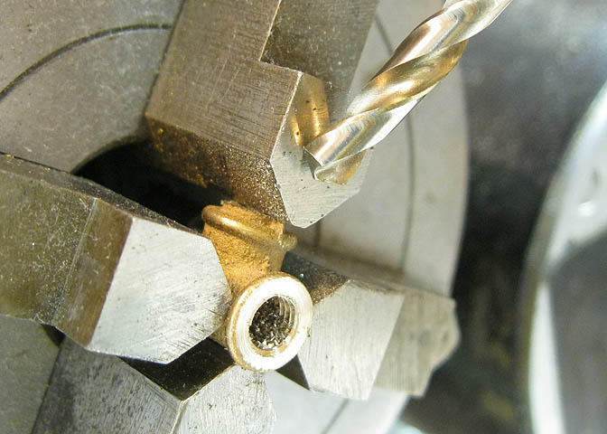
Now the ends need to be swapped to finish the piece. The drill bit in the picture above points to the jaw that pressed
against the unfinished elbow flange.
That jaw is removed from the chuck. A second jaw perpendicular to the one just removed is
loosened slightly, and the elbow is removed from the chuck.
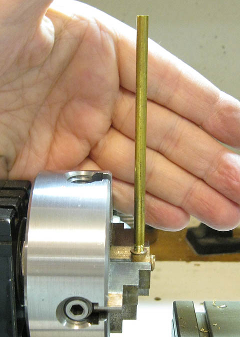
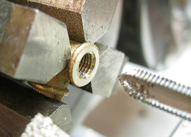
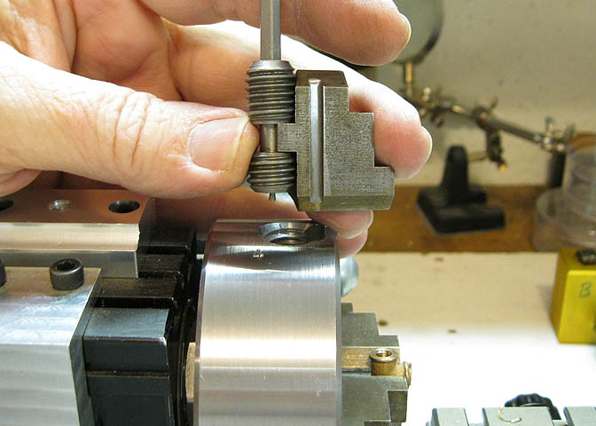
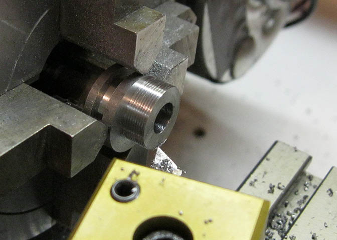
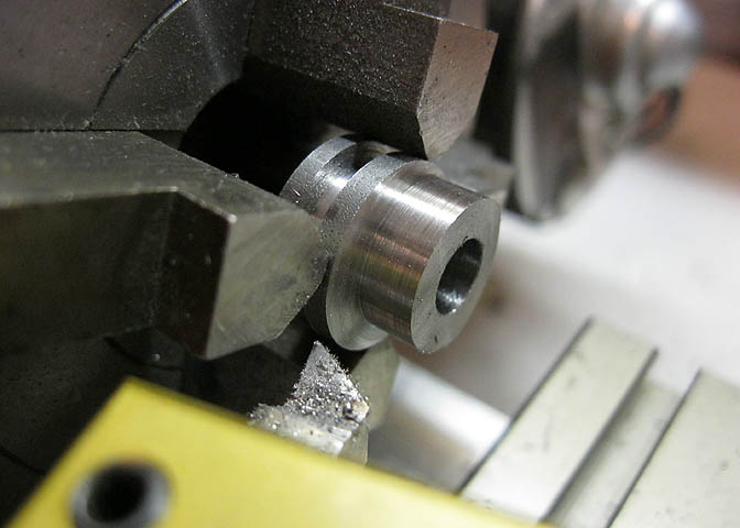
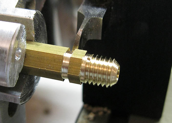
Now a piece of pipe is screwed into hole that was previously tapped, and it is used to assure that when the piece is
tightened in the chuck, the elbow will have holes that are actually at 90 degrees. When you have it set the way you
want it, tighten the same jaw that had been loosened in the last step so the piece will be held firmly. Do not disturb
the other two jaws. At this point, the piece should be well set for the next machining steps, so the jaw that had been
removed can be replaced and tightened down. Then it is a matter of repeating the steps above to drill and tap the
second end of the elbow. That should be it.
I've since made a jig to do this which makes things easier. I'll do a page showing that jig sometime.
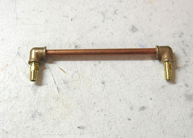
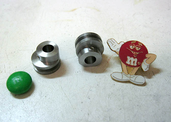
Here are the two elbows that were done today, along with a couple of short nipples that were made during this session.
I didn't show making the nipples. They are just model pipe that I ran a die over to cut the threads.
In the finished model, I ended up not using this piece. A small change to the way the prints show things
was implemented to allow a slightly different setup for use with the governor. The governor for this engine
is a separate kit, and will be shown in part 5 of this write-up.
Also made the valve couplings. Not much to show in making those.
The eccentrics are of CRS. Don't know what kind, as it is an anonymous piece that came in the kit.
The end is faced off and then a parting tool is setup to cut the groove needed for the end of the eccentric rod.
The groove is wider than the parting tool, so after the first cut the tool is backed out and the carriage moved
over the required amount to finish to the proper width.
Then the piece is parted off to length to have it ready for the next step.
Note the pip in the center of the parent stock. My parting tool bit is a little too high.
The next step is to drill the off center hole that will cause the eccentric to rotate off center too. That's
what makes the eccentric rod and valve go to and fro.
I started this piece in the independent four jaw chuck, and since I had it centered in the first step, I could
alternately loosen one jaw and tighten its opposing jaw to offset the piece the needed amount.
The piece is then center drilled, drilled and reamed to fit on the crankshaft. Two of these will be made, and
after the first one is finished two of the jaws on the chuck are loosened and the second piece put in place of
the first. This way I don't have to clock in the second one.
When you use an independent jaw chuck in this manner and do a number of pieces, you must be sure to always loosen
and tighten the same two jaws on the chuck. I have the jaws on my independent chucks stamped with numbers, (1-4)
to easily identify the jaws, and then am always sure to use only jaw #1 and #2 when changing work pieces that
are intended to be identical.
Finally, the turning on the end of the piece is done. You can see a number of rings around the piece in the picture
above. That is from taking a number of facing cuts to reduce the thickness of the piece here.
The final cut is just a couple thou to clean up those rings.
That's them, done. I didn't show the drilling and tapping steps for the set screws. I think there is enough
of that earlier in the article.
The gland nuts for the rear cylinder head are being done in the pic above. The hex rod has been
turned down to diameter to take the threads and then threaded with a die.
The center is drilled so it will pass the piston con-rod.
Then the piece is parted off. After this, a second one is made.
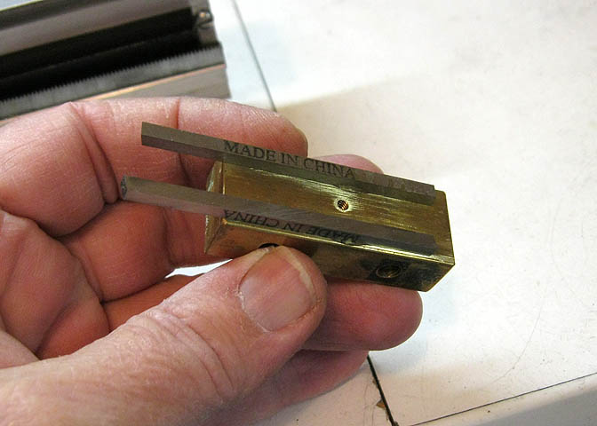
I want to do the machining on the outboard heads. Using super glue, a couple of pieces of square tool bit are
glued to a piece of flat stock. This is to make it thick enough so when I put the work piece against it, it will
still stick out of the jaws enough to do the turning.
(These "made in China" tool bits are good for spacers and things like that. They are ground fairly square.
Some of them are even good enough for cutting metals, and to be honest, some of them are not.)
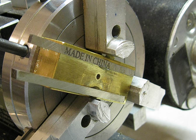
Put it in the chuck.
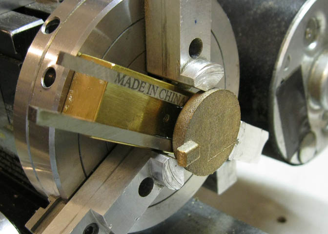
And the piece is pressed against it firmly while the jaws are tightened. Then the backing piece
is removed from behind the piece by pulling it straight out.
For safety's sake, you must not run the lathe with something like this block left in. Even if it seems
snug in the chuck, it will most surly get spit out when the lathe is started. Someone will get hurt.
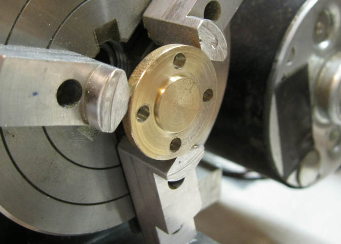
The work is just simple turning and drilling. This was drilled while it was in the lathe, using an auxiliary
spindle mounted to the lathe carriage. The holes were indexed with an index plate I have attached to the
head stock pulley.
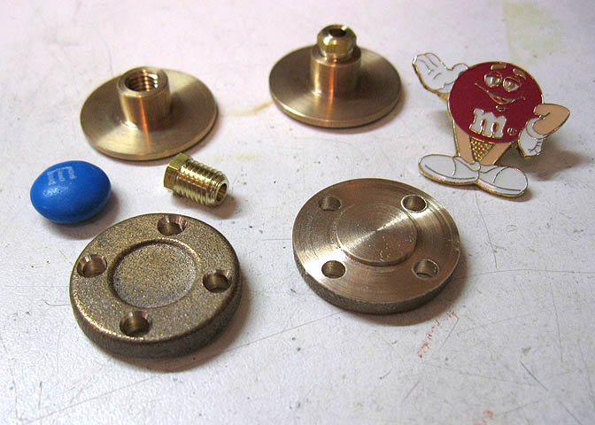
Another parts shot.
These are the eccentric rings. They get a small bevel put on each side. Since they were a factory drawn tube
before they were cut up and put in the casting kit, they are not perfectly round. Very close, but they still need
to be clocked in on the four jaw for each bevel cut. If they were just put into a three jaw, and cut, the error
stacking between the chuck and the slight out of round shape of these rings would cause the bevel to wobble
slightly, and the appearance would be of a bevel cut that looked wider in some spots and narrow in others.
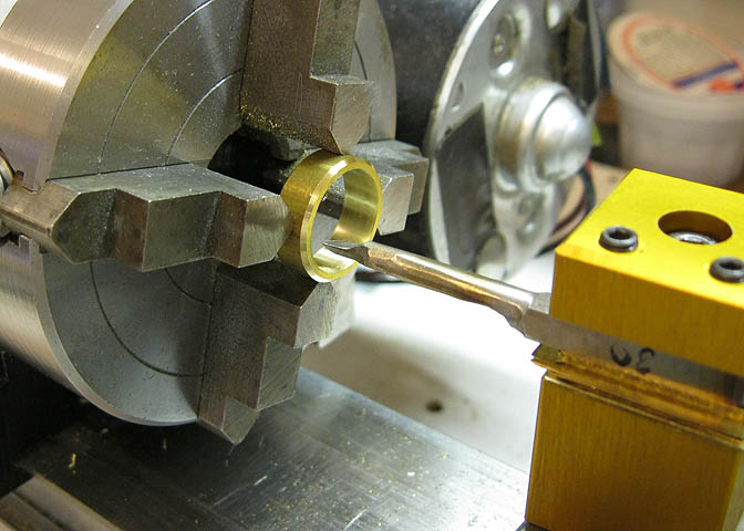
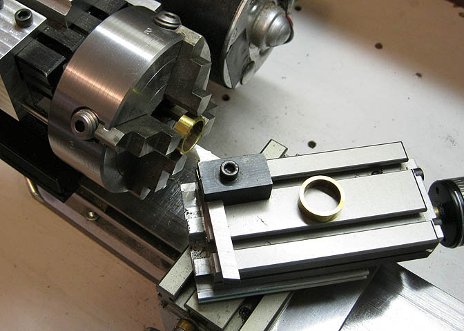
Once the bevels are cut, the inside is bored to size for the eccentrics.
You have to take care when you chuck up tubing, so as not to get the chuck jaws tight enough
to cause the tubing to become deformed. If you get them too tight, after the hole is bored and
the jaws loosened, the hole in the piece will not be round.
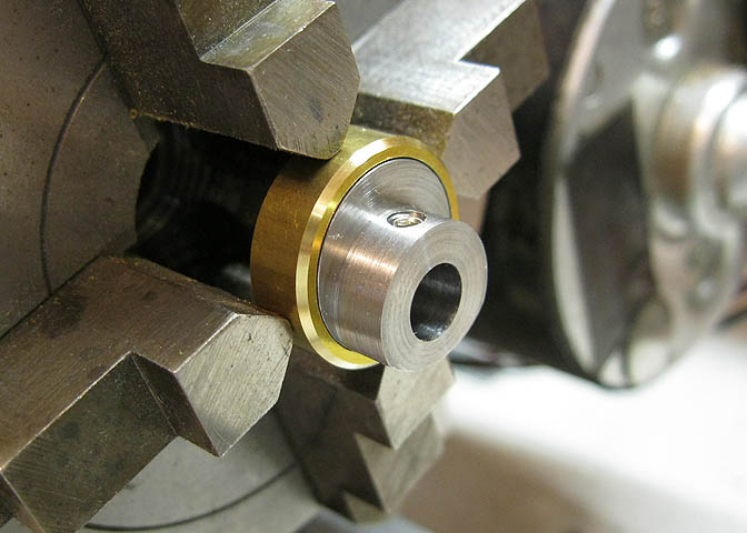
Checking for fit here. They need to be a close fit, but still have clearance enough for the pieces to turn free.
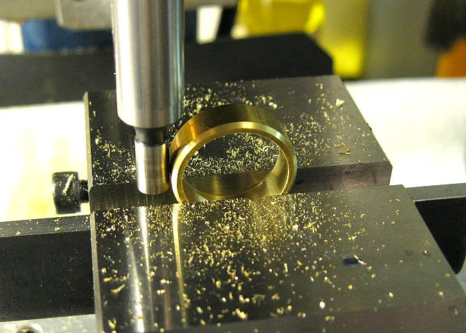
Last step on these is to drill and tap for the eccentric rod. A small spot face is put over the tapped hole, too.
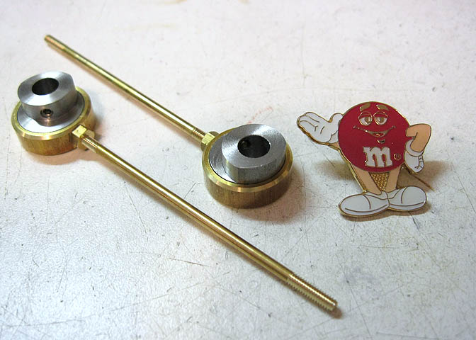
I threaded the eccentric rods, too. They still have to be bent to shape, but that comes after the cylinders
have been done up and installed on their supports.
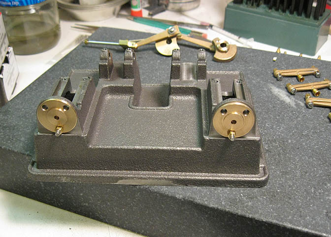
Last thing for this page was drilling the base to match the inboard cylinder heads.
These took some time. I don't get a second chance on them, so easy does it.
Go to Part 4
Back to:
Part 1
Part 2
Part 3
Part 4
Part 5
More Taig Lathe & Mill Projects
Copyright 1998-2010 Dean Williams