Building the PMR-7 Twin Cylinder Steam Engine
Part 5 (and finish!)
This is a governor kit from The Steam Chest designed by Eccletors Devices, that is meant to fit the PMR-7 engine.
The "kit" consists mainly of a bunch of small cut pieces of bar stock, along with a few brass balls and a spring.
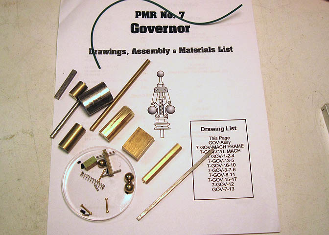
It comes with a set of prints, and though you get dimensions for the needed pieces, I don't care for drafting style.
The prints for the PMR-7 engine are top quality, and done following proper drafting conventions, which make things
very clear. These for the governor are not so good, done in a thin-line style with arrow lines placed willy-nilly
on the drawings, and improper dimension lines. They have all the dimensions needed despite my gripe. I just prefer
things on prints to be done right.
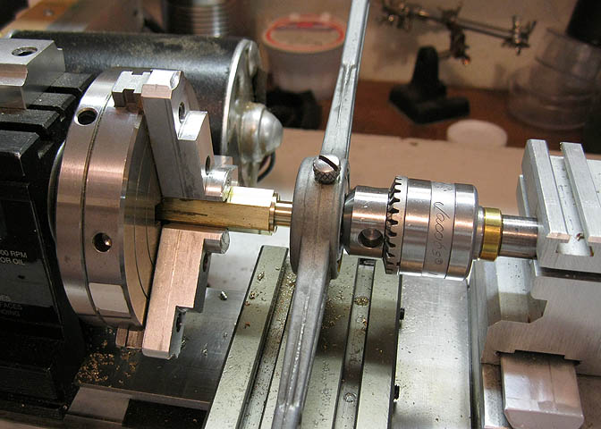
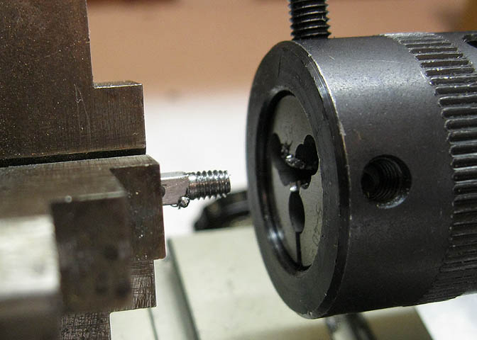
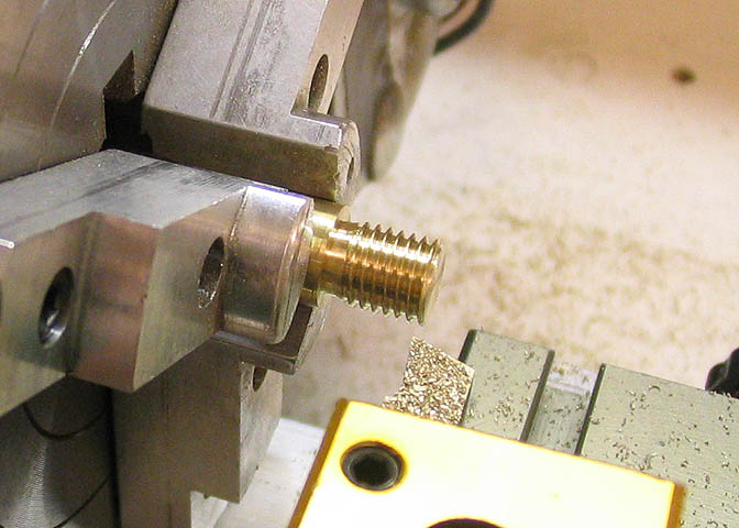
I started with the governor pillar, which will screw into the engine base. A piece of hex stock is turned down
to threading size, and a die run over it to put on the threads. The type of die I happen to have in the needed
size is a hex shape, and really I would consider it a thread chaser. It worked for this, never-the-less. I used
the tailstock chuck to keep the die flat against the work piece, so the threads would be reasonably true.
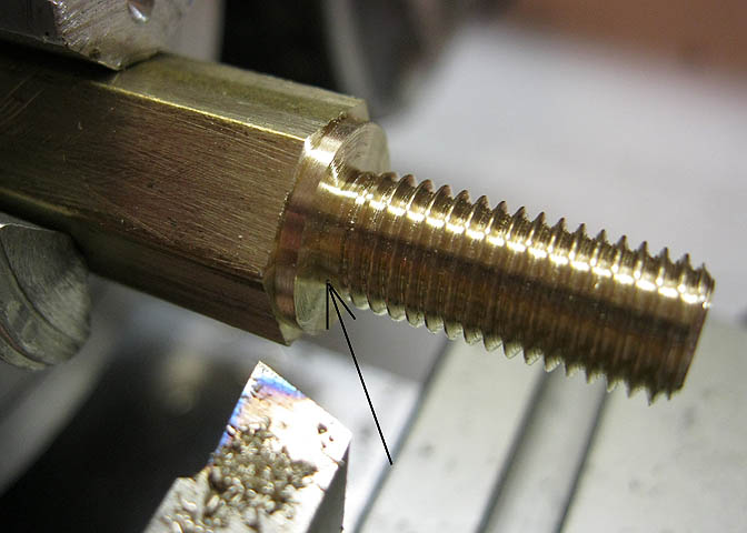
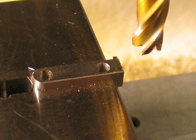
The die will not thread right up to the shoulder here, so I cut away the place where the last thread would lie,
so the piece will thread all the way into its hole.
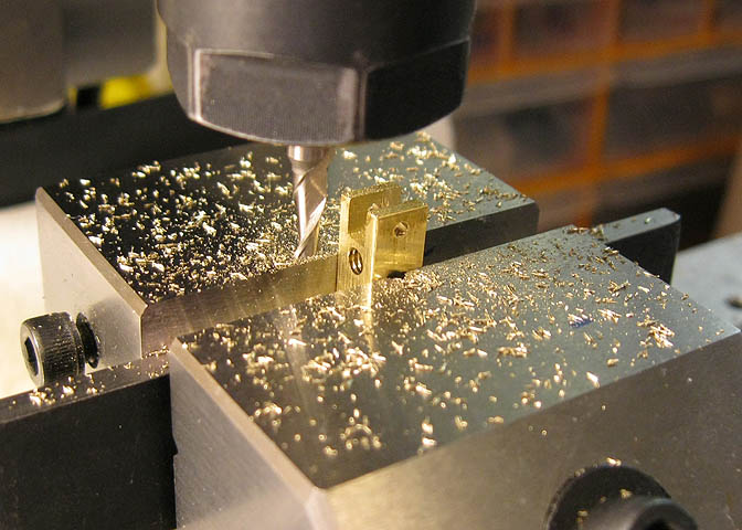
Next will be the pivot block for the governor ball arms.
It's mainly a block with a few holes and slots. After a little file work on the corners, it was done.
The governor arms are of 1/8" square stock, and here are being centered in the four jaw.
The ends of the arms are turned round and threaded. The brass balls will go on here.
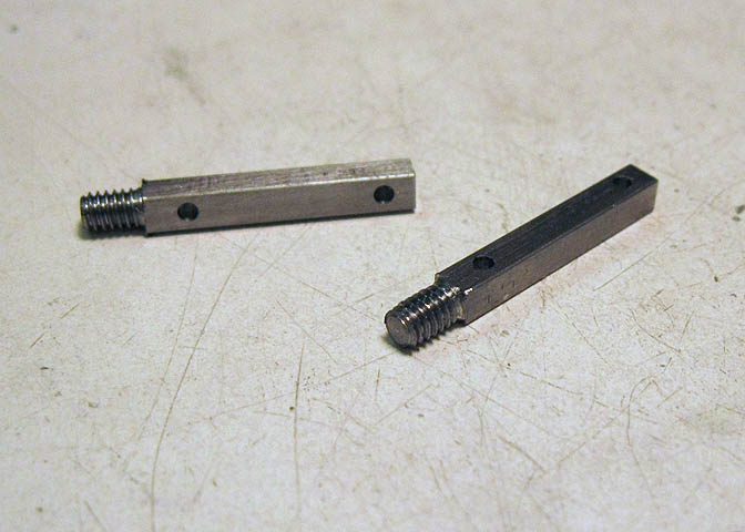
That's the arms done, except for a bit of clean up work.
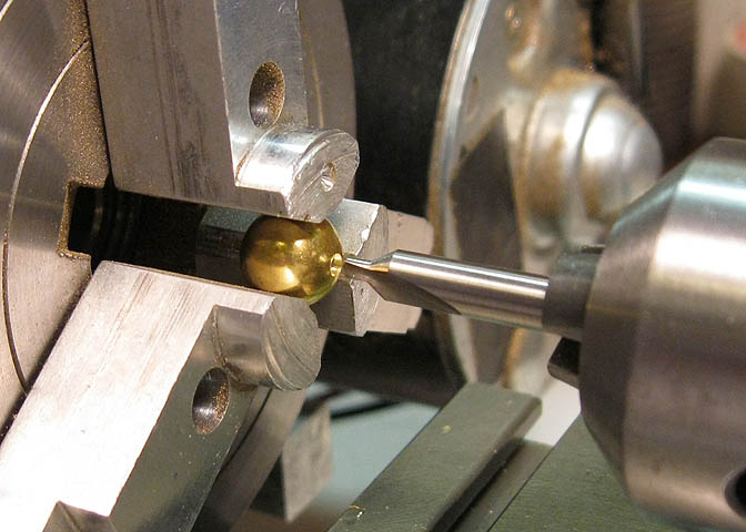
The brass balls are drilled and tapped same thread as the arms.
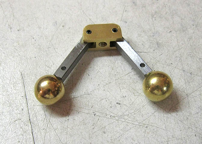
The ball arm assembly.
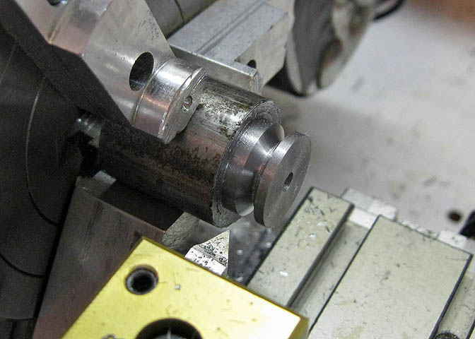
The governor needs two pulleys, one that goes on the right eccentric on the crankshaft, and one for the governor
spindle. A piece of CRS is turned down to the proper diameter, then drilled down the center.
Then the belt groove is cut with a threading tool.
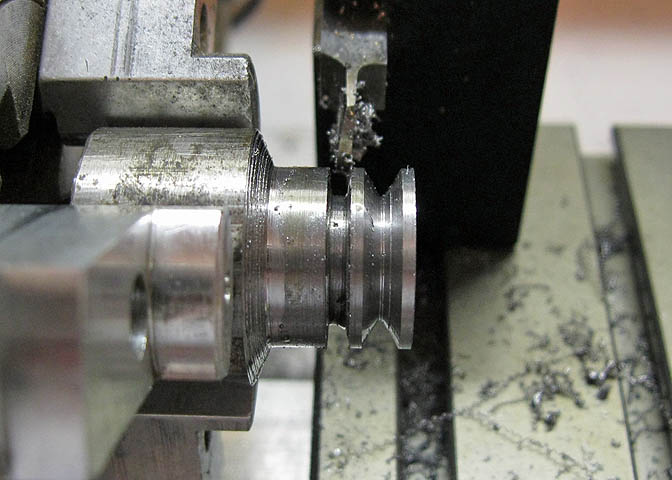
Then it's parted off.
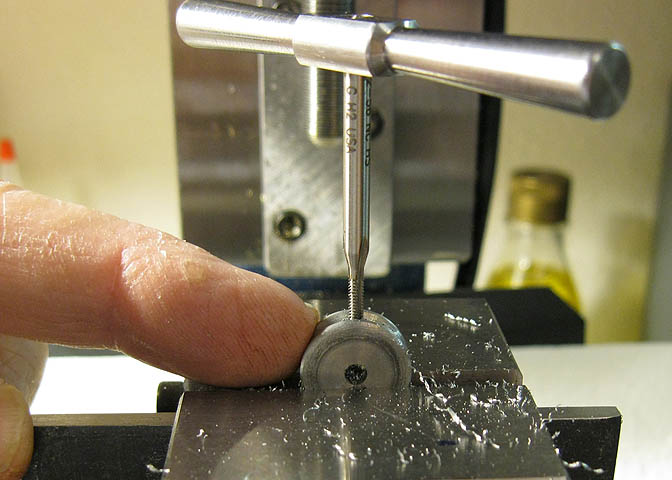
Finally each pulley is tapped for set screws. One 4-40, and one 2-56.
The slide has been turned and moved to the mill. The top is milled down and a couple of holes drilled.
The follower is started in the lathe too, then it goes to the mill to put on the flat sides.
Here they are.
And they will go together like this.
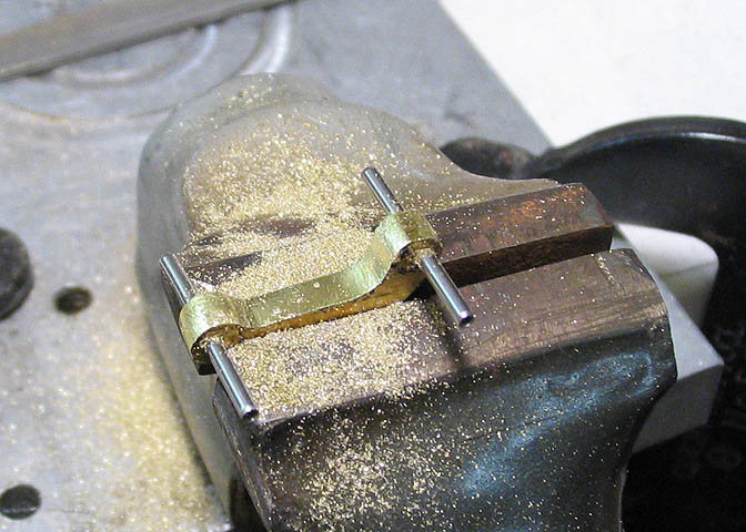
The slide arms start out as four pieces of sheet pinned together. The pins go through the holes that
will eventually connect to the ball arms and the slide.
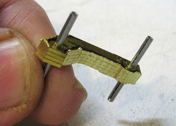
The excess metal is roughed out on the mill.
Then I get after them with a file.
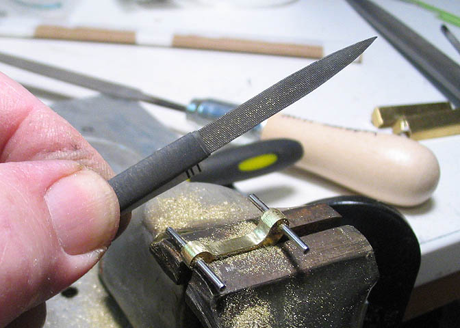
Finally the pieces are papered. That just means wrapping fine wet/dry sanding paper around the file
so I can work on the pieces and keep the edges crisp. If you do don't put the sand paper on something
flat, it will round over edges, which is not what I want.
This is the start of the valve stem.
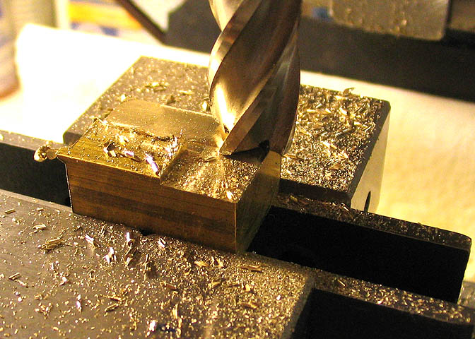
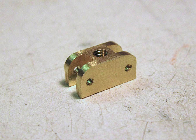
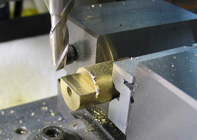
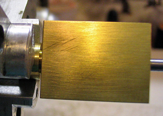
For the valve block, a piece of brass is milled all over.
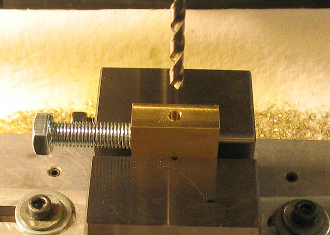
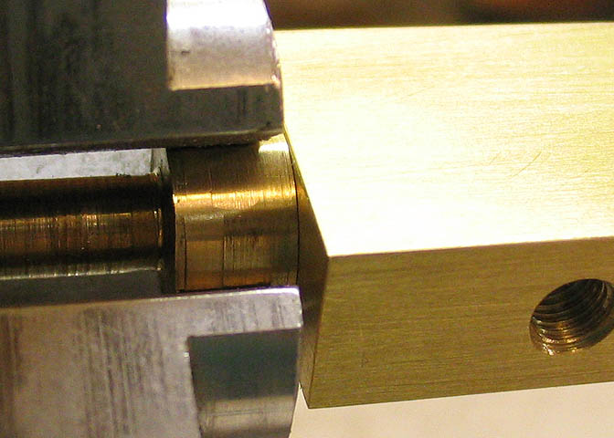
The block gets a few stepped holes drilled through and the end tapped for a steam fitting.
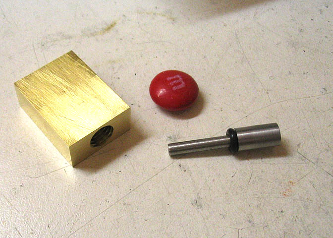
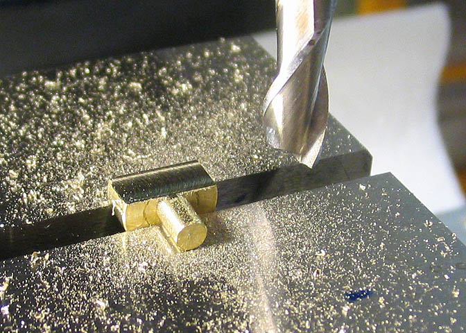
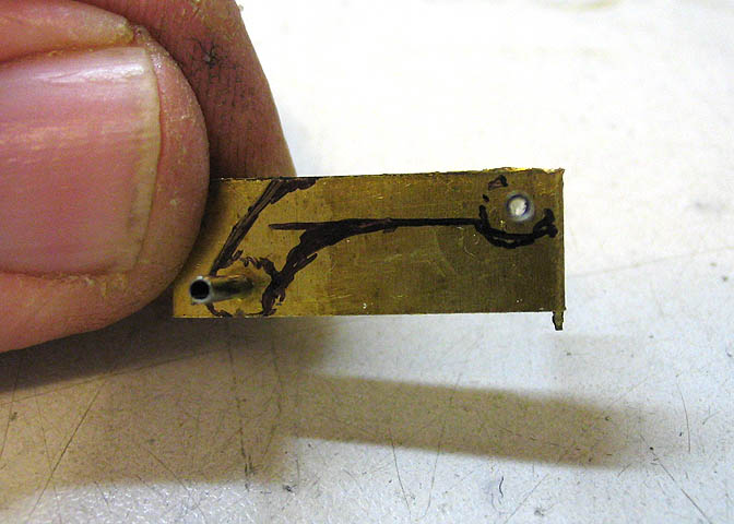
Here is the block and stem. Now the stem has to be put in the block, and the steam passage drilled
through both pieces at once to make sure the holes align properly.
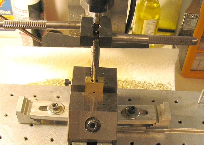
To make sure the stem doesn't try to walk it's way out as the steam holes are drilled, a stud is put
into the threaded hole in the end of the block to hold it firm against the inside of the block. Then
the steam passage is drilled through the whole thing.
The holes in the sides are tapped for the steam pipe.
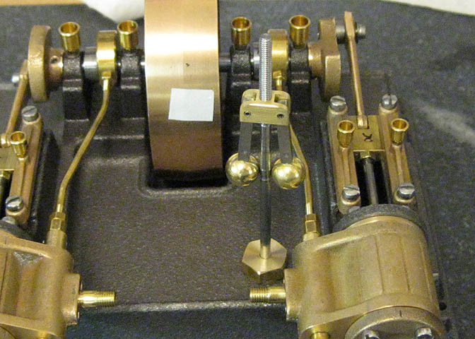
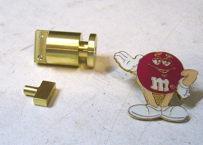
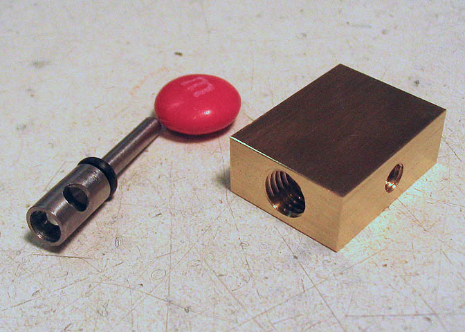
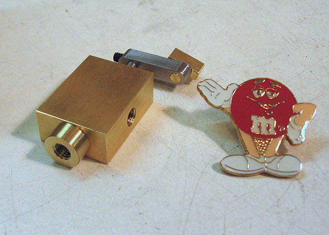
The valve itself (left) fits in the larger hole in the valve block. As the governor spins, a lever on
the valve rotates it, and the hole through the valve diameter becomes more, or less, aligned with
the steam inlet in the valve block. Thus, more or less steam is admitted to the steam chests on
the cylinders, which increases or decreases the speed of the engine.
The arm that will rotate the valve stem is just a piece of square stock drilled for a couple of holes.
One hole goes over the valve stem, and is fastened with a set screw. The other hole will hold the governor
follower, which rotates freely in the hole, and also slides in the groove in the bottom of the governor.
As the governor spins faster, the follower is raised up, which rotates the valve stem and changes the flow of steam.
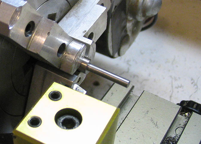
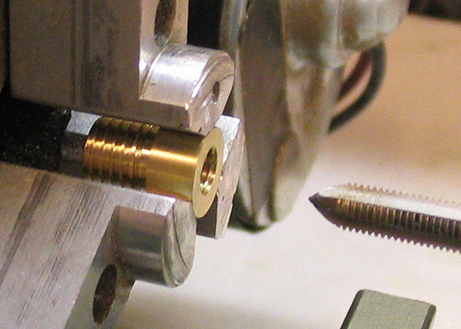
Time to make the steam bushing that will go in the end of the valve block. A piece of round stock is turned
down to proper size for threading the part that will go into the valve block.
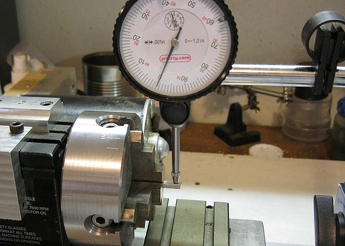
The bushing does another job, besides passing steam. It also sets the end play on the valve stem. Here, I'm
checking to see how much needs to come off the end of the bushing so that when it is screwed in flush to the
surface of the valve block, it will also hold the valve stem inside the bore in the block with .005" end play.
After a few tries, I get it right. It only took four fit-ups and a few minutes to get this done.
Finally, the bushing can be drilled through and tapped for 3/16" steam pipe.
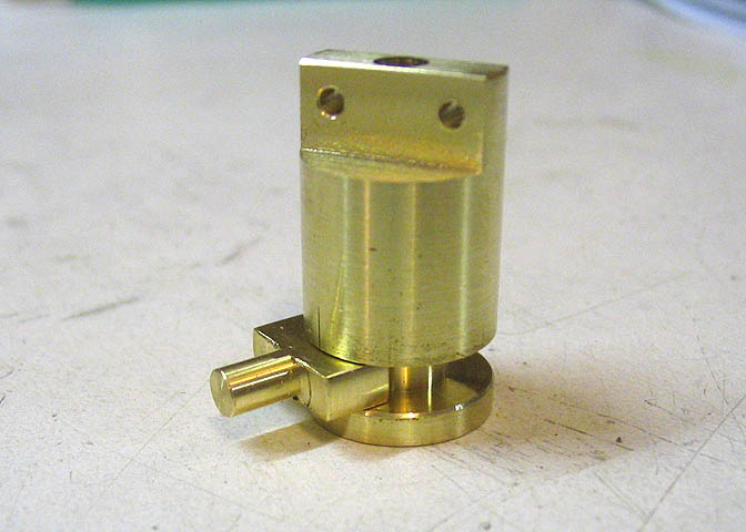
The completed valve assembly.
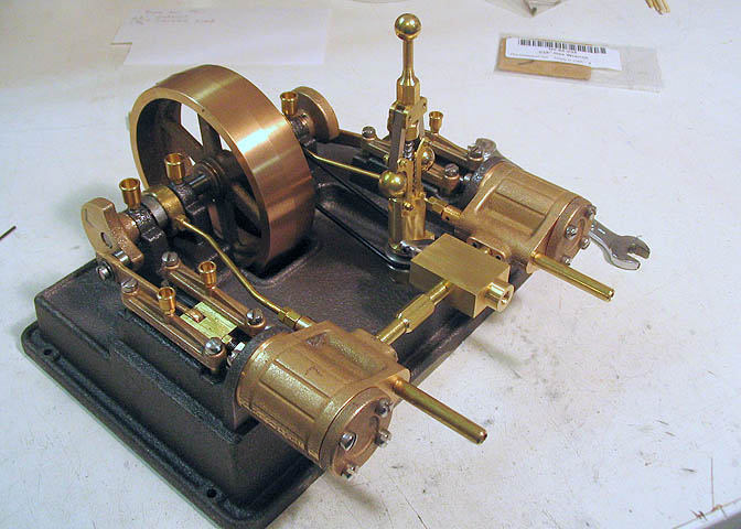
The completed engine and governor.
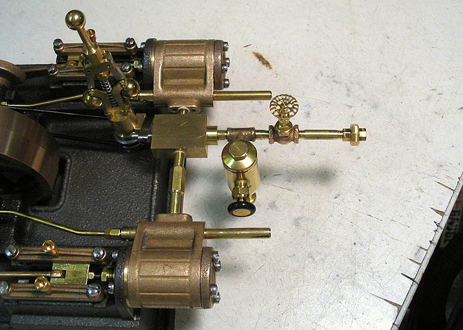
Another shot, showing a couple of accessory pieces that Phil sent for fitting up.
The globe valve and lubricator are both PM Research stock items. Quite nice, too.
That's it for this build.
Here is a video of the engine running on air. I left steaming it to Phil, the owner.
It has since been shipped to Sweden and has been steamed many times.
Back to:
Part 1
Part 2
Part 3
Part 4
Part 5
More Taig Lathe & Mill Projects
Copyright 1998-2011 Dean Williams