Building a 4" Rotary Table
Suitable for the Taig Mill
Part Four
Milling the T-slots.
One thing that needs to be mentioned before continuing; A collar was cut
on the lathe and tapped for a 6-32 set screw. The collar keeps the worm shaft from
sliding in and out while it's in use. This is a temporary collar until I get around to making
something more appropriate.
The assembled rotary table is now mounted on the mill table, squared and centered
under the spindle. A piece of 1/4" drill rod can be chucked in the spindle and used
to find the center of the table by aligning it with the reamed hole in the table top.
The first slot is cut using a 1/4" end mill. It goes from the outside rim of the table top to just shy
of the inner alignment ring near the center of the table. The finished depth is .270", but each
cut is only .020 deep, (except for the last one...) Using a good quality carbide end mill, (Atrax,
in this case), each slot only takes about eight minutes. If coolant is used, it can go a bit faster,
but not much. The table top is made of A36 (common hot rolled) steel, and it's not known for
it's good machining qualities.
After each slot has been milled, the table locking clamps are loosened and the table is advanced
to the next position. Since there are not yet any index marks on the table or dial yet, I just counted
the rotations of the crank handle. Starting with the crank at the bottom (6 o'clock) position, the crank
is turned 15 times, ending up with the crank back at the bottom. The worm is 60:1, so each turn
of the crank is 6 degrees. Fifteen turns of the crank gives 90 degrees, so there will be four
equally spaced T-slots.
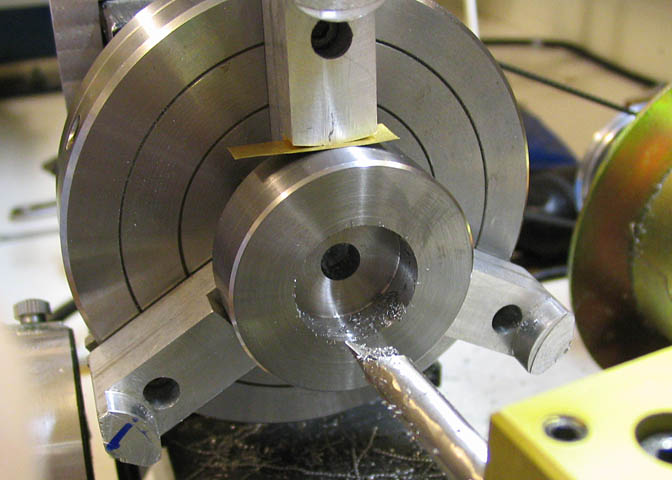
Cutting T-slots is a two step process. First, the center of the slot is milled, as in the picture above.
Then the "T" cutter is run down the center of the milled slot at the required depth.
So, with the four slots milled, it's time to cut the "T" part. Time to make the T-slot cutter.
The T-slot cutter is made of drill rod. The slot in the table should be about .390-.400" wide for using
#10 square nuts, which is what will be used with this table. I didn't have any drill rod in 1/2" dia., so
I just made the cutter using 3/8" instead. It will make the slot a close fit with the #10 square nuts, though.
I'll just make T-nuts to fit later on.
The blank is turned in the shape of the needed cutter. The end is the full diameter of the drill rod, (.375),
for .150" length.
The smaller shaft diameter is .225" for .350" long. The remainder of the shaft is left at it's original
diameter, which fits a collet perfectly.
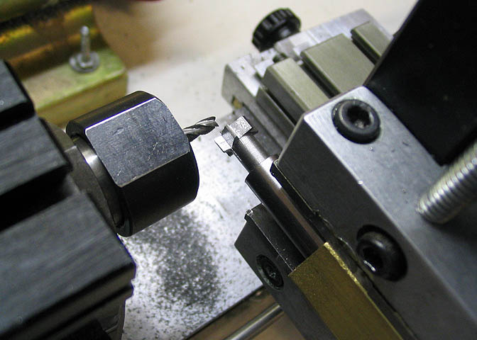
This cutter should have been made earlier in the game. As it is, the rotary table is on the mill,
set up for milling the T-slots, and I don't want to disturb it. So, the cutter to finish the "T" in the
slots that have been milled will have to be made on the lathe using a milling attachment.
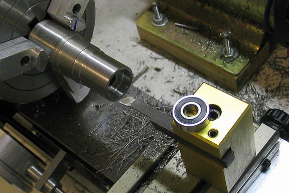
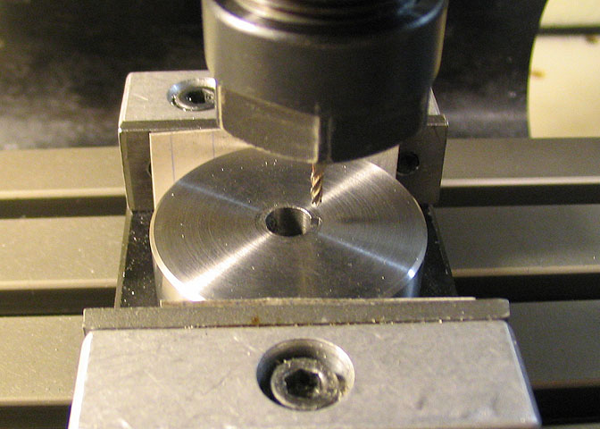
The cutter has six cutting edges, and to index them for milling, the cutter blank is held in a hole
that has been reamed in the center of a piece of hex rod. That way, each edge can be cut by
simply rotating the hex rod one flat for each cut.
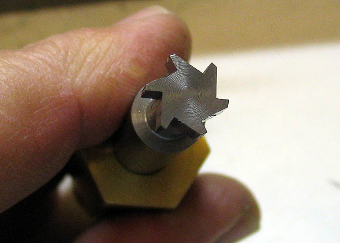
After the first round of cuts the cutter will look like this. The flat on the end of each tooth still has to
be milled down some to provide the majority of the relief for the cutting edges. The cutter is rotated
just a bit in the hex rod, and another round of passes are made on the back side of each tooth, just
leaving 10-20 thou of the original flat on the end of the tooth.
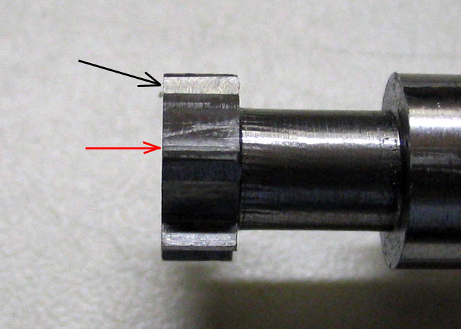
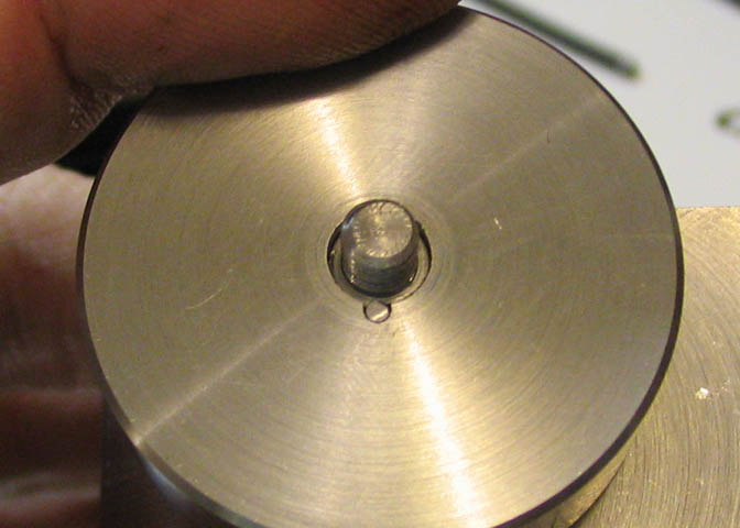
The black arrow shows the back of the tooth after it's been milled for the relief. The red arrow
shows the very tip of the tooth. (The arrows are pointing to different teeth.) There is still a small
flat on the tip of the tooth at the red arrow. That little bit still needs to be relieved in order to cut
properly. This last bit was done with a fine sharpening stone, then the front of the tooth is honed
with a hard Arkansas stone. Then the cutter is then hardened and drawn.
Close up shots like this really show a guy's faults. The chatter left by the cut off tool is
very evident. Tsk, tsk...
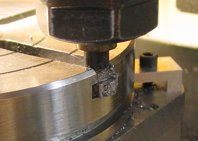
This is the first "T" being cut. My mill has a minimum spindle speed of 525 rpm, and in my opinion
that is a little fast for a cutter of this type made of drill rod. The cutter had to be re-honed three times
per slot. By the time I had finished the third slot, this first cutter was worn out. Actually thinking
ahead for a change, I had made two of these cutters, so there's no problem getting the job done.
It's certainly possible that the first cutter dulled quickly because I didn't get it hot enough with the
propane torch I used to heat it for hardening, too. There have been a lot of tools made in my shop,
and mistakes in hardening happen now and then. Another one of those things that "just happen".
After all this work, (well, it's not really work, 'cause I enjoy it),
there is now a functional rotary table sitting on my mill. No way to calculate radial
motion yet, since there is no proper engraved crank and the table is not engraved
yet either, but it does work. I had to give it a try. I bolted a piece of scrap onto the
table and started turning the crank...
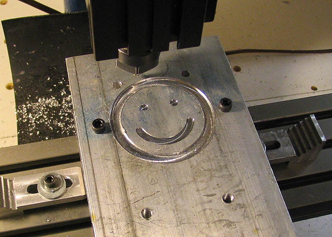
Well, it's all fun and games, after all.
Now, time to get back to "work".
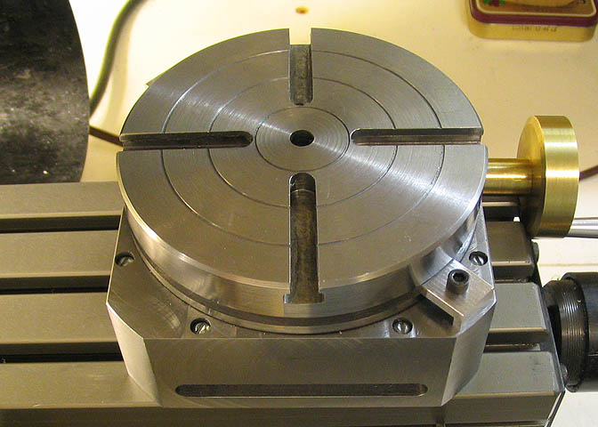
Now with the T-slots cut into the top, the rotary table can help with "building itself".
A piece of flat stock scrap is mounted to the table top. Holes are drilled in this piece of 1/2"
aluminum plate to fit the T-slots, and the holes are countersunk for the screw heads so they
will not interfere with mounting the plate to the mill table. Then the whole affair is turned up-
side-down as shown, and the aluminum plate is bolted to the mill table. The piece of flat stock
may appear askew, and it is. It already had a number of holes drilled in it, and I just used a
couple that were available. The position of this plate doesn't matter, really, since the edges
of the table can be squared up simply by turning the handle on the table.
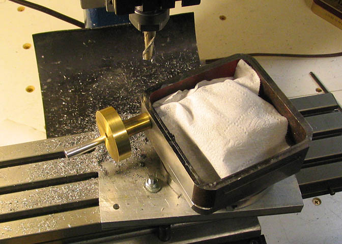
To square the table, I went off the surface of the Z axis ways. When square, center of the
table is found using the edges of two perpendicular sides. Then the position of theoretical
corner is found using the X and Y dials of the mill.
The piece of tissue over the worm and gear is to keep swarf out of the works.
Finding the theoretical corner doesn't actually put the end mill over anything that can be milled. It
will just be hanging over thin air, since the corners of the square tubing that the base is made from
are not actually corners. They're a crude radius. But, finding this imaginary corner gives a starting
point, that is, a zero point for dialing in the X and Y axes.
From here on in, the X and Y dials are always dialed to the same amount, and both before each
cut. To start, I dialed each in .050", lowered the end mill to make a cut of about .025", and cranked
the rotary table until the end mill had made a cut on the corner, (making sure to keep the backlash
out of the worm, and feeding only into the cutting edge of the end mill!). After the cut, turn off the
mill, crank the rotary table back, feed in another X and Y increment, and make another cut.
This continues until just a line of the old base surface is left, and then the X and Y increments are
decreased to a few thou until a clean radius appears from edge to edge. At that point, the X and Y
readings are written down for use on the other corners, and the radius is cut all the way down to the
top of the base, lowering the spindle about .020-.030" per cut.
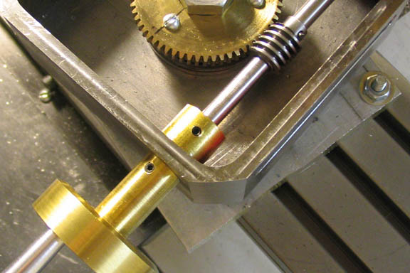
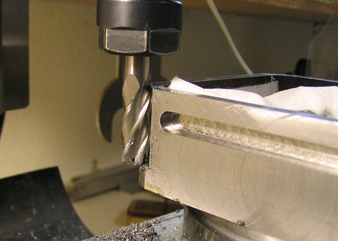
When each corner is finished, it will look like this, which is a bit nicer than the original finish
of the square tube as it came from foundry.
One note on this; When the time came to cut the corner nearest the crank handle, the handle
was in the way of the end mill. It's easy to solve this problem. Take out the worm shaft, flip
it end for end, and put the handle on the other side of the table.
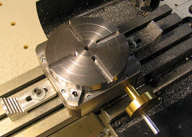
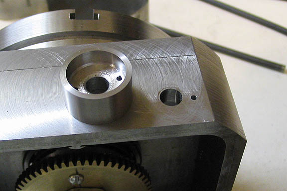
Some kind of bearing is needed for the crank, and there's really not enough material
in the wall of the base for it, so a bearing housing is turned from 1018 CRS. This
could be made from any kind of steel. The housing is .750" in dia. It has a 1/4" hole
drilled through, (about 3/4" deep is good for the work piece), then a recess is bored
for an R4 bearing, .625" dia., and .200" deep. The piece is parted off to a length
of .430".
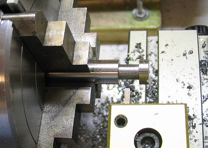
After parting it off, the housing is mounted in the chuck with it's back side facing out
and a face cut is taken to remove the bur from the parting operation. The finished length
is .425". Then two opposing holes are drilled on a .5" circle. Hole size is 1/16".
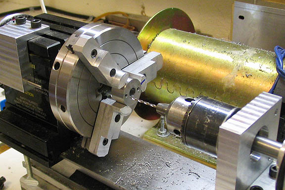
The bearing housing is just held on with two 1/16" pins. The holes were located by
first putting the worm shaft in the base, then sliding the housing over the shaft. The first
hole is spotted using the hole that is in the bearing housing, then the housing is removed
and the hole is drilled through. To locate the second hole accurately, put a pin through
the first housing hole and through to the hole just drilled in the base. Put the worm shaft
through the base and into the bearing housing. and the second hole location can be
spotted with a 1/16" through the second hole, and it can be drilled through same as the first.
Once this is done another pin is put through the second hole. The pins are made from any
convenient 1/16" dia. rod. I used common hardware rod, but drill rod will work great too.
If the pins are a little loose in the holes, they can be bent very slightly right in their middle and
they will hold the housing snug for the time being. Eventually, they will be made more
permanent with some Locktite.
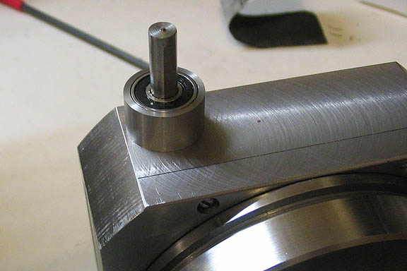
With the bearing pushed into the housing, this step is done. If the bearing ever needs
to be removed, it can be pushed out from the back by driving pins through the pin holes.
A thin washer is placed on the bearing so when the dial is attached it will not rub on the
front of the bearing housing.
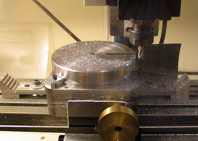
This piece will be the dial. It's 1.5" in dia., and has a .250" hole reamed in the center. A recess
is bored for the dial to sit over the bearing housing, .300" deep and .001" over the diameter of
the housing. The bottom of this recess needs to be flat. The tool seen in the photo above may
look like a boring bar, but it's actually ground specifically to remove any radius in the corner of
the recess that may have been left by the boring bar that was used to bore the hole. It has a
slight hook on the end that comes to a sharp point that will get right into the corner.
A small slot is milled at one point on the edge of the reamed hole in the dial. This slot amounts to
75% of the diameter of the 1/16" end mill being used, and is 3/16" deep. It will hold the larger part of
the diameter of a small dowel that will keep the dial from spinning on the worm shaft.
The worm shaft is 1/4" in dia., and has been turned down and threaded 8-32 for .250" on the end
that will hold the dial. Behind the threaded part, a small "V" groove is filed on the shaft to take the
remaining portion of the dowel pin that protrudes from the slot milled in the dial. The dowel should
be a snug fit in the hole made where the slot and the V groove meet.
Now, the way a real machinist would probably do this operation would be to cut a key way or
Woodruff slot on the shaft, and use a broach to cut the slot in the dial. Seen the price of broaches?
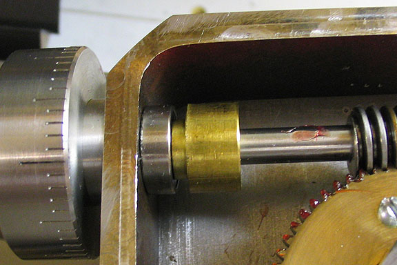
Another R4 bearing is slipped onto the shaft inside the base, and the collar is pushed up
against it and tightened down. This will let the nut on the crank handle be snugged
up without putting the collar in a bind against the base. It can't be seen, but there is
a shim beneath the bearing that rides only on the outer bearing race. This lets the
inner race spin freely, (doesn't rub on the inside of the base).
Go to part Five.
(Yes, there's a part five...)
Part Five
Part One
Part Two
Part Three
Note:
Stephen Campbell followed my progress on this table as it was being built.
I work from a simple sketch, and am not so good using a CAD drawing program,
so Steve very kindly made the drawings going by my measurements. Long story
short, if there should be any errors in the drawings, they are MY fault, not Steve's.
A heartfelt Thank You to Steve for all his good work!
The drawing is in a PDF file, so you need Acrobat to open it, (still free, I understand).
Rotary Table Drawings
More Taig Lathe & Mill Projects
deansphotographica.com
(home page)
Copyright Dean Williams