Building a 4" Rotary Table
Suitable for the Taig Mill
Part Three
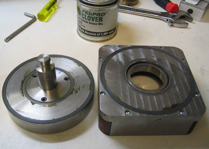
The next step is to make the worm gear mounting ring and bore out the gear.
The worm gear I got was pre bored for 1/4", and had a hub extension of about 1/2".
The gear must go over the .750" shaft on the table hub, and it will have nothing left
for mounting it by the time it is bored for that diameter.
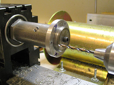
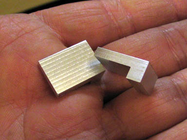
On the left is the gear mounting ring, and on the right, the gear. The ring is 1.5" in diameter,
and is made from CRS. A 1/4" hole is drilled in the center, to match that in the gear. For
work holding, a Taig arbor has a 1/4" dia. shoulder turned on the end so the ring will be held
on the center line of the spindle, and three holes are spotted on a 1.25" hole pattern. The same
hole pattern is drilled into the gear, using the same Taig arbor.
The holes in the gear are then drilled out to pass 4-40 screws, and the holes in the ring are drilled and
tapped for 4-40 threads. You can see my goof on the ring. I had started to spot the holes
without tightening up the arbor on the spindle. By the time I got to the third hole, I realized something
was wrong. I marked the bad hole marks with a marker, and after tightening the arbor, started the
hole pattern again in a different position.
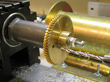
Once the holes are done, a piece of 1/4" drill rod is used to align the gear and it's ring, and the
three screws are tightened down to hold the two pieces together for boring. Then the drill rod
piece is removed from the hole.
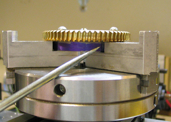
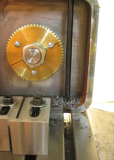
The two pieces are then indicated in with the four jaw chuck. Note that the chuck is not bearing
on the gear teeth, but holding the ring, behind it. The pieces need to be indicated both on the
diameter or the ring, and the face of the gear.
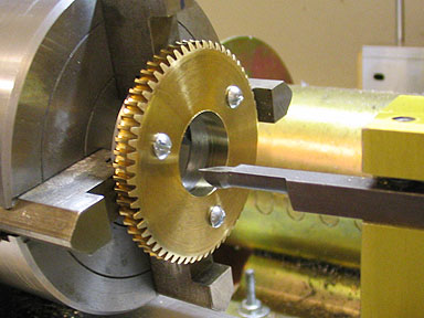
Once the bore for the gear and ring is finished, the assembly goes into the three jaw chuck
for marking out another hole pattern. The holes that go into the edge of the ring are tapped for
6-32 set screws. To save having to tap the entire depth of the hole, half the depth of the hole
can be drilled out to clear the set screw, with just the bottom half being tapped.
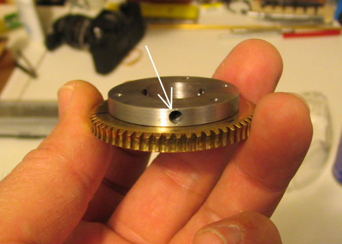
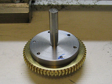
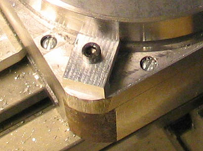
A shot of the finished set screw holes in the gear mounting ring. You can see the other
two holes inside the bore of the ring.
Everything is assembled at this point to help find the location of the set screw flats that need
to be milled in the table hub.
The hub and table are bolted together and laid face down on the bench. Then the base is set on
on the table and the bearing is slipped over the hub shaft and aligned in the race, which will
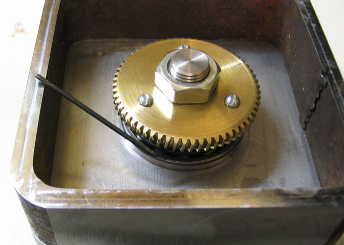
align the parts. The gear and it's mounting are put on the hub shaft, and the jam nut is finally
cinched down to pre load the bearing. It just needs to be tightened down a little. Then use an
Allen wrench to tighten the three set screws onto the hub shaft. They are only tightened a little.
Just enough to make a small mark in the hub shaft.
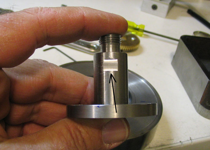
Then the whole thing is disassembled and three flats are milled at the location of the marks
made by the set screws. If this isn't done, and the set screws are tightened down hard on the
shaft without the flats, you won't be able to remove the bearing. The set screws will raise a
bur that will not allow the bearing to pass.
The hub is replaced in its' recess in the table top, and the running surfaces of the table
and base are lapped in. Everything must be reassembled for this step, but the set screws
for the gear ring are not tightened. Clover Compound is used for lapping. I used 150 grit.
The Clover is spread in a light coat on the running surface of the table top, the whole thing
is assembled, and the table is turned 'round and 'round on the base. Turn it five or ten rotations,
tighten the jam nut a little, and turn some more. When it feels smooth through its' 360 degree
rotation, it's done. This took only about five minutes.
Care must be taken not to get the Clover in the bearing. It will ruin it and the race in short order.
When the lapping is finished, everything is disassembled, and all parts are cleaned very, (very)
well. There is always the possibility that some of the Clover will get into the bearing. The bad
news is that it will have to be replaced. The good news is they're cheap. Less than $15.
When everything is nice and clean again, the bearing is oiled, and the whole shebang
is assembled again in preparation for the next step. On assembly, the bearing is pre-
loaded just enough to hold the table top to the base snugly, but not so much that the
table can't be rotated.
Remember the hole that was reamed in the table top, way back at the beginning? Time to use it.
The table assembly is now mounted nice and square to the mill table, and a piece of 1/4" drill rod
is inserted into the hole in the table top. This is used as a reference for finding the center of the
table hub. The edge of the drill rod is found with an edge finder, and the mill table is dialed over
to put the center line of the table/hub/shaft assembly under the mill spindle. Then the spindle is
raised, and the Y axis is cranked to the left so the second co-ordinate can be located off the face
of the gear.
To find the edge of the outer side of the gear a .500" parallel is held against the gear surface, and
the edge finder is used again for a location. Then the pieces are added up, and the Y axis is
cranked back for that amount; The gear is .219" thick. The edge finder pin is .200" in diameter.
Add half the gear thickness, (call it .110"), to half the diameter of the edge finder pin, (.100"), and
the width of the parallel, (.500"), and the Y axis dial in is found: .110" + .100" + .500" = .710".
Dial that in and the spindle will be directly over the center line and in the middle of the gear face.
The last co-ordinate to dial in it the set-over for the worm gear shaft. The diametral pitch of the gear
is 1.875" and the D.P. of the worm is .438". Add those two together and divide by two to get 1.1565",
or, to make it a little easier on the eyes, say 1.157". The backlash is taken up on the X axis, and
that amount is dialed in. An extra thou or two wouldn't have hurt. It's a really close fit, as it is.
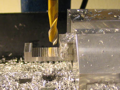
The first hole is spotted and drilled 15/64" through the top surface.
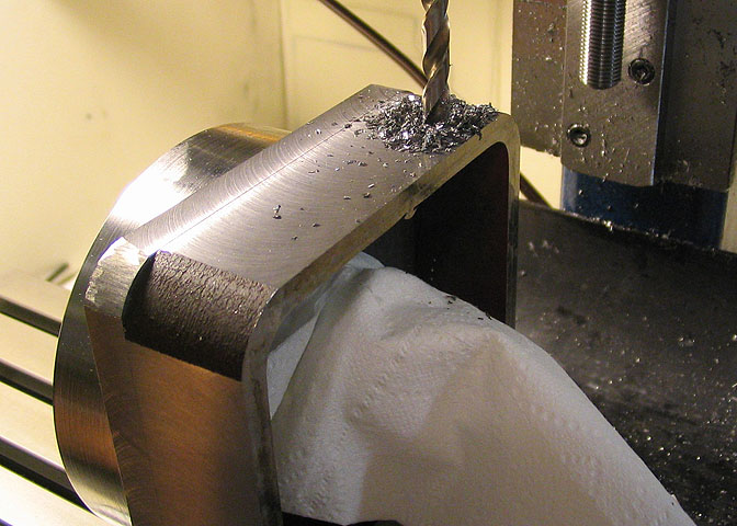
The bottom hole is drilled using an extra long 15/64" bit. This hole has to be started with a
light touch on the Z axis feed so the drill doesn't wander all over. I just got lucky in the shot
above. The location of the hole was centered perfectly over one of the T-slots in the mill table.
The plan was to drill half way through this bottom part, then transfer the piece to the drill
press to finish the hole. As it was, after this hole was drilled, a 1/4" reamer was run through
both holes on one pass, and for the moment, this operation is done. I'll return to it later.
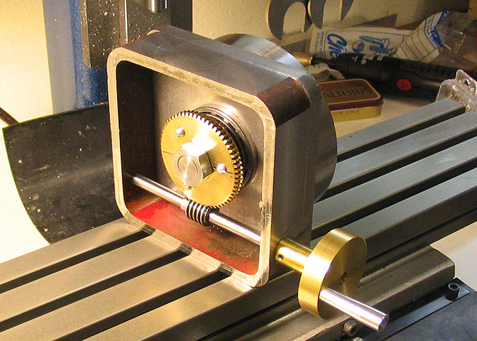
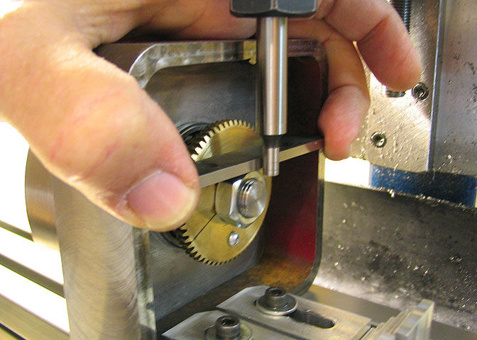
A piece of drill rod and a spare handle are used to check the fit of the worm to the gear. This is
not the handle that will be used for the finished piece.
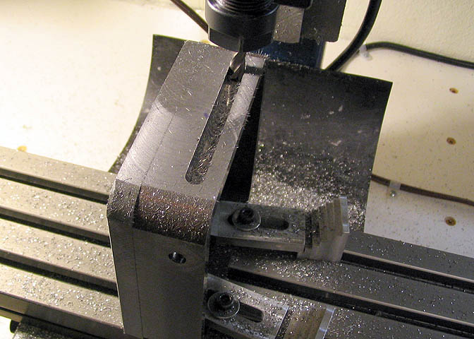
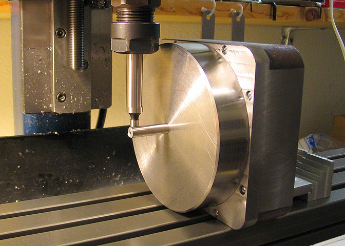
Again, the table is disassembled, and the base mounted on the mill to cut the hold down slots, or pockets.
One slot on the right, one on the left. The two sides with the holes for the worm shaft do not get the slots.
The slot is .270" wide and the bottom edge is 1/4" from the bottom edge of the base. It starts 5/8" from
the front edge and ends 5/8" from the back edge. (The front edge is the one with the hole drilled in it
in this picture.)
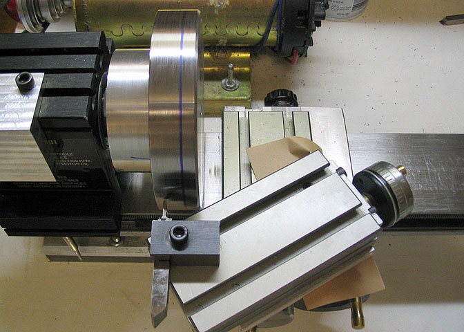
While the table top is off the base, the clamping groove can be turned. The compound slide is used
to get a cut off tool into position for the cut, since the piece is too large to swing over the cross slide.
The groove to be cut starts .125" from the bottom of the table top and is .150" wide and .125" deep.
This takes a while since light cuts must be taken on such a large piece. The brown piece of paper
under the compound provides some friction between the compound and the cross slide to help keep
the compound in place. Without it, the compound has a tendency to slip on the cross slide, since it
is hanging off the front of the cross slide, and the clamp for it is not terribly strong.
The finished clamping groove can be seen in this shot.
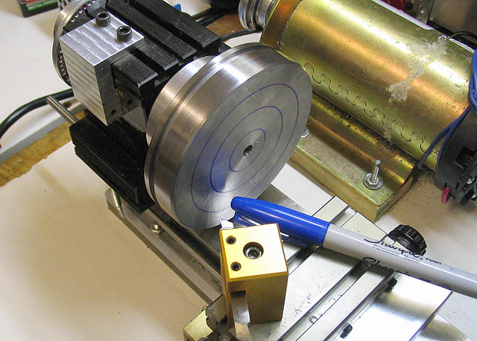
I've used a Sharpie marker to check out the positions of the alignment rings on the top of the
table. They are one, two, and three inches in diameter, and are cut .015" deep and .025" wide.
The next thing on the list are the two hold down clamps that will lock the table.
These pieces have to be made before the next operation on the table top.
When the clamps have been milled out they are drilled to pass a 6-32 screw,
and the top of the base is drilled and tapped for same directly beneath the clamp.
Click on the link to page four.
Part Four
Part One
Part Two
Part Five
Note:
Stephen Campbell followed my progress on this table as it was being built.
I work from a simple sketch, and am not so good using a CAD drawing program,
so Steve very kindly made the drawings going by my measurements. Long story
short, if there should be any errors in the drawings, they are MY fault, not Steve's.
A heartfelt Thank You to Steve for all his good work!
The drawing is in a PDF file, so you need Acrobat to open it, (still free, I understand).
Rotary Table Drawings
More Taig Lathe & Mill Projects
deansphotographica.com
(home page)
Copyright Dean Williams