Building a 4" Rotary Table
Suitable for the Taig Mill
Part Two
Time to work on the base for a while.
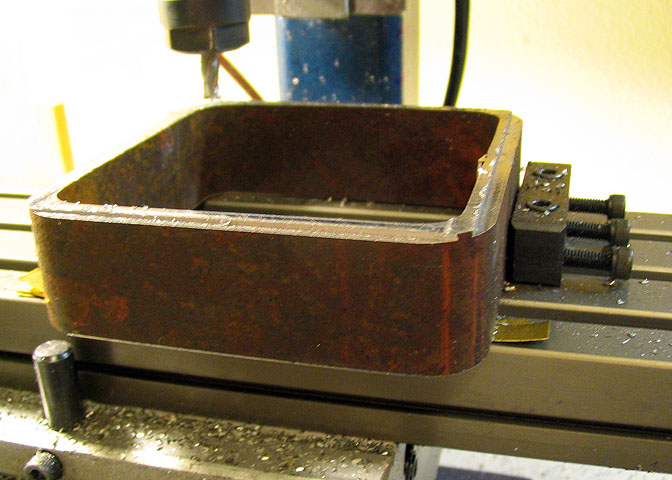
The base is made from two pieces. One is a piece of 3/8" thick 4" x 4" CRS. The second
piece, shown here is sawn from 4" hot rolled .25" wall square tubing. The piece starts out
1.25" long so there will be enough material to square both ends, which is what is being done
in the photo above. The part is held square with a couple of clamping blocks, and shims
are used to get two of the vertical walls square with the spindle, then the side facing up is
milled flat. Then the part is turned over, clamped square again, and milled to final dimension.
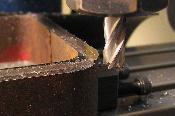
Here's a cut being taken on the second side of the base. This is a .050" depth of cut,
.15" wide, getting the part down to size. A carbide end mill is being used, (Atrax brand).
The final pass is .002" for a nice smooth finish.
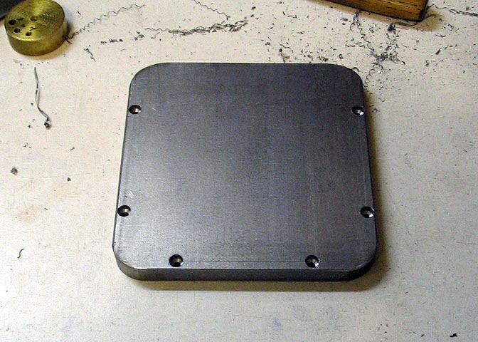
Once the bottom part of the base is milled to size, it's time to go the top plate. This top
plate is 3/8" CRS 4" wide flat stock, cut to a length of 4" (plus just a bit, just to make sure
it isn't less than 4" long). The little bit of over length, which is only about 1/32", will be
cleaned up as one of the finishing steps.
The two pieces, (the flat stock, here, and the large square tube) are held tightly together,
and lines are scribed on the flat stock where its' corners protrude past the round corners
of the square tube. Then the corners are ground down, leaving a little for finishing later.
Three sides of the flat stock should match up with the square tube, with the fourth side
overhanging a little. Now would be a good time to put a couple of witness marks on the
top plate and base piece, to keep them in the same orientation from now on. Then, on
the three sides of the top plate that match up to the base piece, a hole pattern is laid
out, .150" from each edge, and 1" from each corner, and the holes are drilled to pass #4
screws, and counter bored so the screw heads do not protrude. The last two holes will be
laid out later, after the odd edge is finished down to meet the square base.
This is the way that this table was built, but an alternative would be to mill the flat stock
square, and to the size of the large square tube, then lay out all the holes at once. I didn't
have a convenient way to hold the flat stock for edge milling, and I knew I wanted to finish
all four sides of the two assembled pieces later, so I did it the way it's described above.
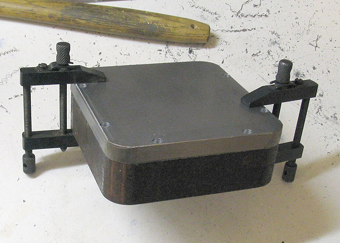
Now the top plate is clamped to the square tube, remembering to match up the witness
marks, and the same drill used for the #4 screw holes is used to spot hole positions in
the square tube. Then the top plate is removed and the holes in the square tube are
drilled 1/4" deep for tapping 4-40 threads.
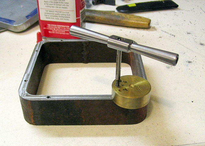
A good sharp (new) 4-40 tap, and a tapping block are used to tap the holes, then a
bottom tap is run into the holes to tap out the bottom. Use lube like Tap Magic or
anything similar. Almost anything is better than nothing.
A tapping block is really handy when tapping small holes. It can be made out of any
small piece of scrap that is square on both ends. Just drill holes through it that will
barely pass the taps that you want to use.
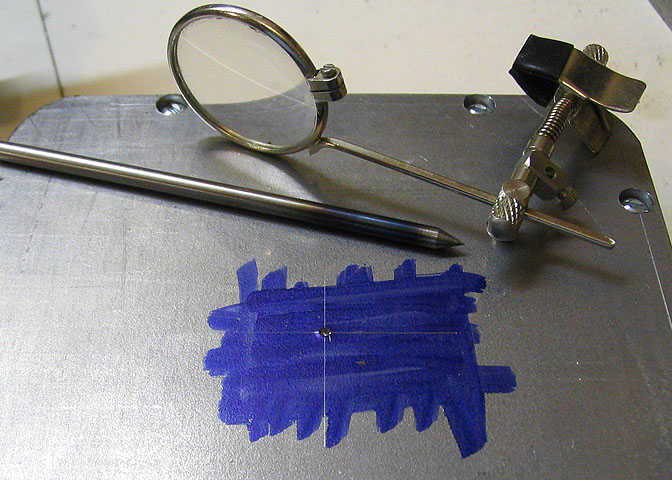
The top plate is attached to the square tube base piece, and a center hole is marked out.
Using an eye loupe and a sharp punch will help locate it accurately.
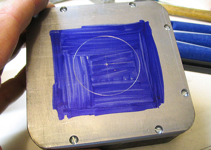
Then a circle is scribed with a compass. This circle is a little smaller than the bearing
race, and is used as a guide for machining out the bore for the bearing. I use it as
the point that I start measuring the bored hole during the boring process.
Now, I need to remove all the metal in the center of the top plate, but the plate won't
fit on the my lathe to bore it. Another way to do it is to drill a large a hole as possible,
(which is about 9/16", in my shop), and then use a boring head with a very small
boring bar in the mill. Well, I haven't got around to making a boring head yet...
The last resort would be a metal cutting hole saw. Strike three. Haven't got one.
There is another way to do it, which is pretty easy, considering all that is needed is a
drill press and a jewelers saw. Here's how.
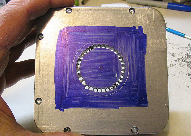
A second circle is scribed on the top plate, about 1/2" less in diameter than the first circle.
The circle is then punch marked at about every 1/8" of the circumference. A 1/8" drill bit
is used to drill through every second punch mark. Then the 1/8" bit is swapped for a 3/32"
bit, and all the holes that were skipped the first time 'round are drilled. Using the 3/32" bit
is to keep the drill from wandering into one of the previously drilled holes, and ruining the cut.
Once the second half of the holes is drilled 3/32", put the 1/8" bit back into the drill press,
and drill out all the 3/32" holes. You will end up with a bunch of holes that just barely run
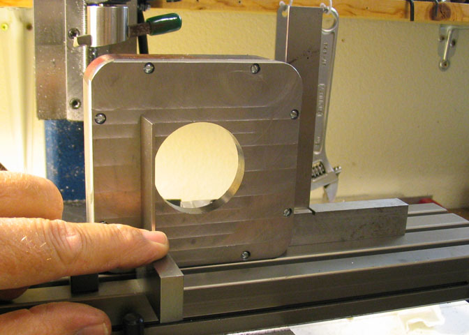
into each other. A few will still be connected, which is where the jewelers saw comes in.
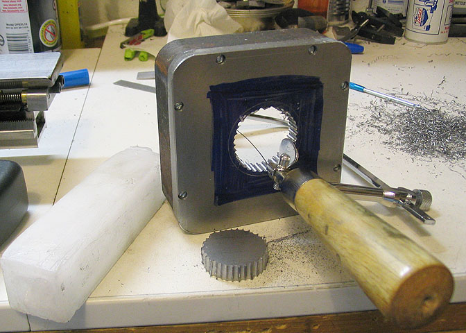
Thread the blade through one of the holes and cut through any pieces that are holding the
center of the top plate. It will just fall out when you have cut all the places between holes.
Use paraffin to lube the blade on the jewelers saw.
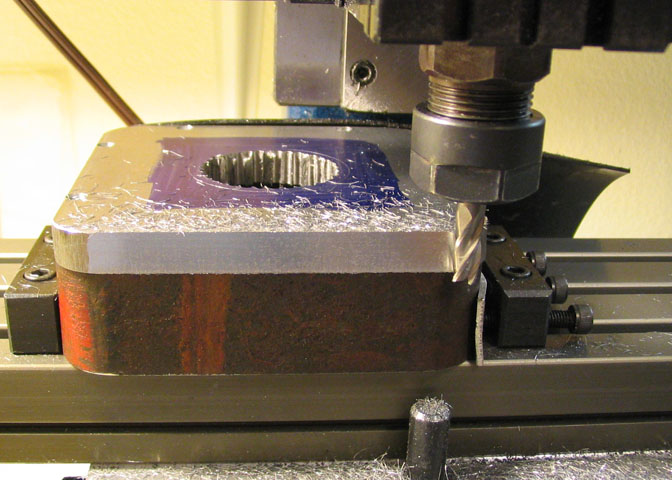
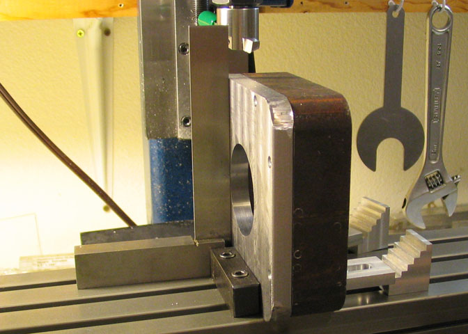
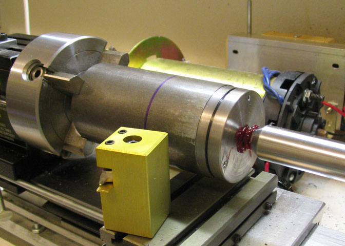
The piece is put on the mill for boring the hole in the top plate. First, that one odd side
of the top plate was protruding a bit past the edge of the base piece, and it was just
bugging me, so I milled it off. Then the piece is centered by finding two perpendicular
edges (with an edge finder!) and dialing in the center using the X and Y micrometer dials.
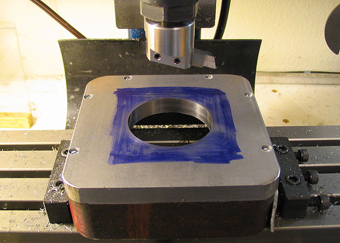
This shows the finished bearing bore, and as can be seen, I used a fly cutter in place
of a boring head. This hole has to be accurately cut to allow a proper fit with the race, so
it takes a bit of careful fiddling to get the cutter in just the right place for the final cut.
It's explained in the next paragraph.
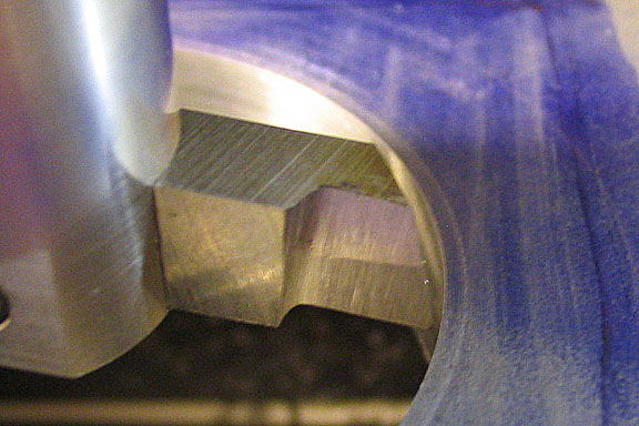
The tool bit is actually positioned using the X travel micrometer dial. After a cut is made,
the mill is shut off and the tool is positioned with it's cutting edge pointing directly toward the
X ways dial. Since a cut has just been taken, the bit will be in a relationship with the work
piece where there is no space between it and the work piece, but it is also not touching
the work piece. Like it's in tool bit limbo... The tool has to be lowered just a bit into the bore,
and make sure the X dial is zeroed and the backlash is taken up for travel to the right.
Now, if you want to take a cut of .002" off the dia, dial .001" right travel into the X dial. (Lock the gib.)
Loosen the tool bit in the fly cutter, and gently push it to the right until it touches the bore of
the work piece and tighten the bit. Raise the spindle so the bit is clear of the bore. Unlock
the X gib, rotate the X dial for travel to the left, past zero enough to take up the backlash,
and then back to the right to zero. The work piece will now be back to its' original centered
position, and the tool will be positioned to make a cut that will increase the diameter .002".
It may sound like a lot of fidgeting, but lacking a boring head, it works well. You have to
work carefully and methodically to get the cut you want. Go slow.
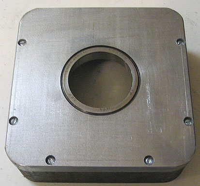
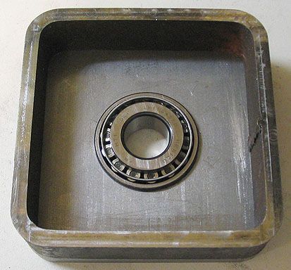
Test fitting the race and bearing in these two photos. The race is an easy press fit.
A machinist reference book will tell the interference tolerances for various classes
of press fit. I just made this as close to a zero tolerance bore as I could. In other words,
I made the bore for the bearing race the same size as the race itself, (as close as I
could measure it, at least). The race pushes into the bore with a moderate amount of
of force. It can be started into the bore squarely with a drill press, then tapped home
with a piece of hard wood against the race, and hitting the wood with a mallet.
To remove the race, turn down a piece of aluminum stock to the same size as the
race, hold it against the race, and tap it out with a mallet.
Time to fly cut the sides of the base. For the first side, there is no way to really
tell if any surface is square, except for the top and bottom of the base since they
are the only two surfaces that have been machined. For the first side, the base is
clamped to the mill table so that the top plate is square to the table. The tube that
base is made from is hot rolled steel, so even though it's a piece of square tube,
it's not really square. This first cut will square the side to the top. It took quite a few
shims under the work piece to get the top plate square. Once everything is set,
the first side of the base is fly cut.
After the first side is cut, flip the piece so the newly cut side is resting on the
mill table. At this point, I also turned the piece "long ways" on the table. For
the first cut, I had it positioned "cross ways" on the table so I could check my
square easier.
When the second side is cut, they should parallel, and square to the top plate.
The third side is cut after the piece has been clamped to the table using shims
to make sure the top plate and other two finished sides are square to the table.
The fourth side is done in a similar manner.
Back to the lathe to make the table mounting hub. I went at this a little backwards,
but that was just to save some material. I had a four inch length of this 2" dia piece
of 12L14. I wanted to save as much of the piece as I could for another project.
Obviously, it's been center drilled for the dead center. It has also been spotted with
the same bolt pattern as was used for the rotating table, as these two pieces will be
mated for assembly. In order to get a cut started without trying to plunge a turning tool
straight into the piece, a groove has been cut with a parting tool just shy of the finished
length of what will be the large end of the hub.
After the piece has been turned down a bit, another cut is made with the parting tool,
and left and right hand tools are used alternately to turn the piece to either end of the cut.
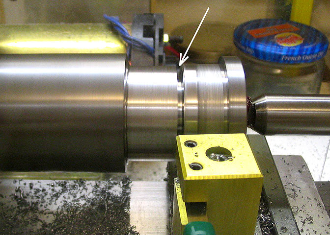
When the shaft part of the hub gets to down to .750", it's done for a moment. The piece
removed from the lathe, and the hub is cut off with a hack saw.
The hub is then indicated in on the four jaw, as shown, and the small end is turned down
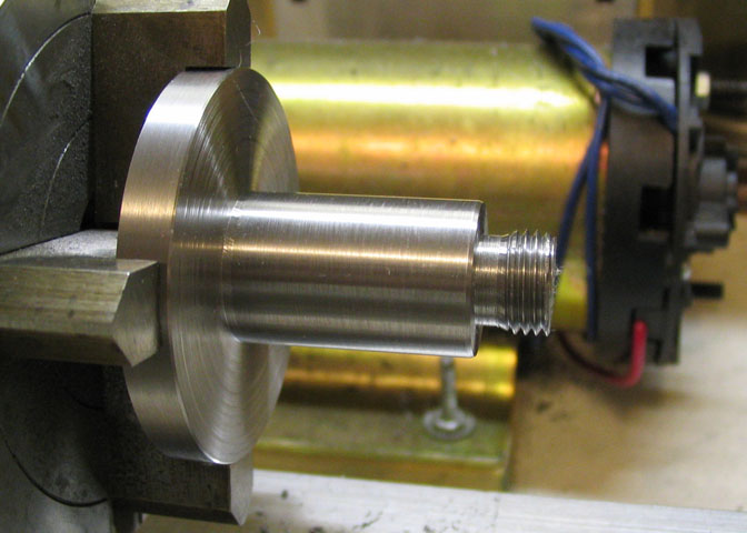
for the required length to take 1/2-20 threads. Since the threads are cut with a die, which
will not thread all the way to the shoulder, a relief is cut just behind the threads to allow a
nut to run all the way to the shoulder.
The finish on the running part of the shaft does not have to be mirror bright, but the
diameter must be exact. It has to fit into the bearing with no perceivable play, but
it cannot be so close a fit that it galls.
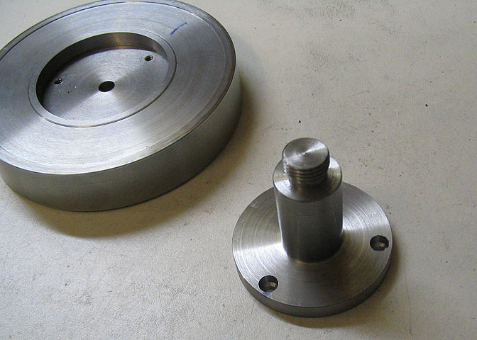
When the piece is finished in the lathe, the holes that were spotted on the end of it are
drilled through to pass a #6 screw, and the side that has the bearing shaft is counter-
bored for #6 socket head cap screws.
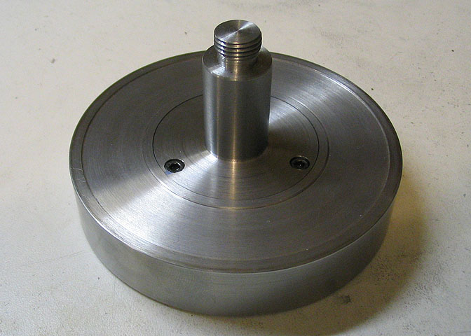
Whatd'yaknow... It fits.
Time to click on the link for part three.
Part Three
Part One
Part Four
Part Five
Note:
Stephen Campbell followed my progress on this table as it was being built.
I work from a simple sketch, and am not so good using a CAD drawing program,
so Steve very kindly made the drawings going by my measurements. Long story
short, if there should be any errors in the drawings, they are MY fault, not Steve's.
A heartfelt Thank You to Steve for all his good work!
The drawing is in a PDF file, so you need Acrobat to open it, (still free, I understand).
Rotary Table Drawings
More Taig Lathe & Mill Projects
deansphotographica.com
(home page)
Copyright Dean Williams