Building a 4" Rotary Table
Suitable for the Taig Mill
Part One
This is something I need in the shop. I could buy one in the flash of a
credit card, but I can also build one, and it's an excellent project for the small
shop. Unlike other projects that can practically spring from the parts box, or
the local salvage yard, there is some outlay required. The main purchase is
the worm and gear, which can cost around $50. Most of the other materials
can be found in the scrap pile, though, and a trip to the local welding shop
or scrap yard will probably turn up the needed bits.
The nominal table size is 4", and the base is 4" across.
This table should fit on most small mills. The worm and gear are 32 pitch with a
ratio of 60:1. With a little extra figuring, a 72:1 worm and gear can be squeezed
into the base, but for my needs, the 60:1 ratio will work fine.
The worm and gear I used are from Stock Drive Products, U.S.A.
Gear: A 1B 6-N32060A
Worm: A 1 C55-55N32
The large bearing is numbered BR2, but I think there is a better number on the drawing.
The two small bearings are simply marked R4 and if you look for shielded bearings on the
Enco Tools web site you can find them there.
Stephen Campbell followed my progress on this table as it was being built.
I work from a simple sketch, and am not so good using a CAD drawing program,
so Steve very kindly made the drawings going by my measurements. Long story
short, if there should be any errors in the drawings, they are MY fault, not Steve's.
A heartfelt Thank You to Steve for all his good work!
The drawing is in a PDF file, so you need Acrobat to open it, (still free, I understand).
Rotary Table Drawings
First, a shot of the table, then the construction notes if you're interested.
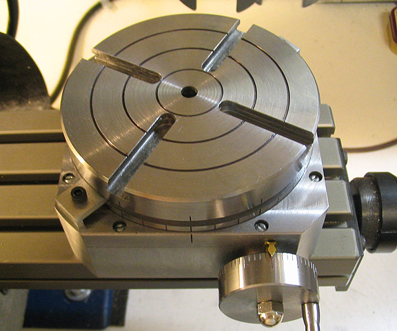
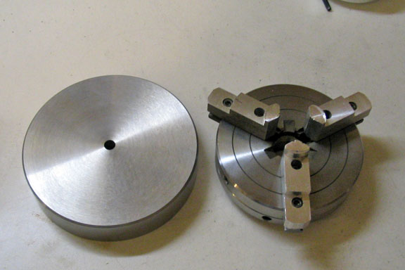
Here's where it all starts...
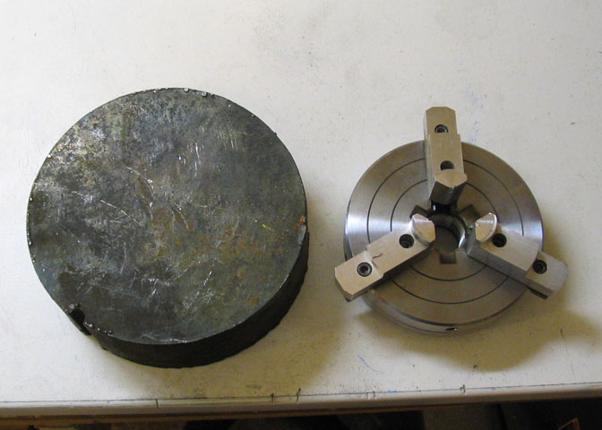
Well, nothing like starting with a problem at the beginning of a project. The piece on the left
is what will become the table, and obviously it's way too big for a Taig lathe chuck.
I got this piece from a welding shop scrap pile. It was what was left of a hole that was cut
in thick mild steel plate. If I were starting over, I would put out a little cash to buy a piece
cut from round stock. It would have saved me a lot of time, as will be seen...
First, since the piece will not fit in a chuck, a face plate must be made for the lathe. The
Taig machine company sells ready made face plates for their lathes pretty cheap, and I'm
going to buy some soon. But at the moment, I don't have one. I've just never needed one,
and never remember to order one when I place an order from them for things like tool posts
and spare belts.
I had a piece of 2 3/8" diameter aluminum round stock left over from some other project. It's
about 1.5" long, but the length doesn't really matter. The ends are faced off, and a hole bored
to take threads for the 3/4-16 spindle nose on the Taig lathe.
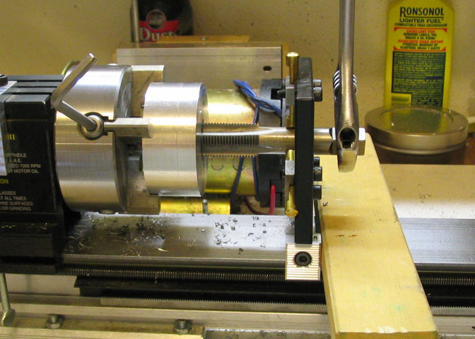
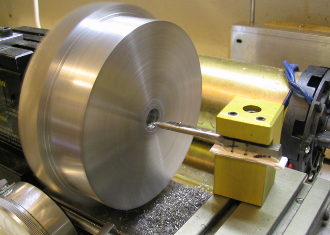
Once the tap hole is bored, tap it for the Taig spindle. The steady rest was used to keep
the threads going straight. The chuck is held with the hex tool normally used to adjust the
jaws, and the tap is turned with a wrench, as shown. The piece of wood on the lathe ways
is to protect them in case I slip with the wrench.
The belt is removed from the head stock pulley while the hole is tapped, just to keep
things from flying around the room in case the motor is switched on.
After tapping the hole, a relief is cut in the bore to let the face plate sit flat against the
spindle nut on the lathe, the same as Taig does for their chucks.
The last step is to cut a bevel where the back of the face plate and the bore meet.
Just about any angle will do for this as long as it takes off the sharp edge left
by the tap.
Take the face plate out of the chuck and mount it on the spindle, then face it
off so the front of the plate will be square to the head stock.
Now a three hole pattern is spotted on the face, (front) side of the face plate.
Best to make this pattern to match the table mounting hub that will hold the table to
the base of the completed rotary table. See the drawing.
After spotting these holes, drill through holes for #6 screws, and counter bore the
holes to within 1/4" of the front of the plate.
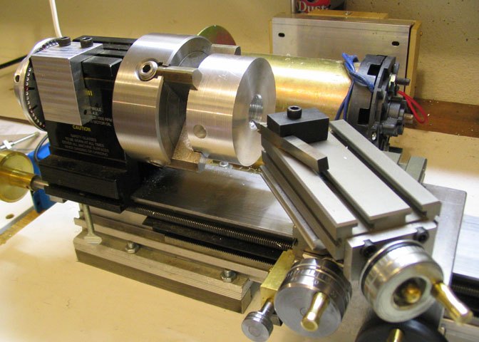
The setup for indexing the holes can be seen on the far end of the head stock. There
is a write-up for that on the Projects page, or index plates can be bought ready to install
from Nick Carter.
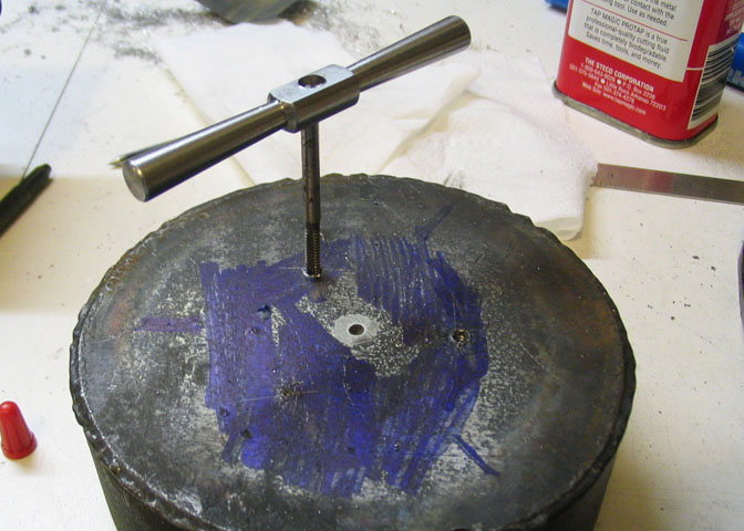
The plate that will become the table is now drilled and tapped for mounting on the
face plate. Drill for a tapped hole for 6-32, 3/8" deep. Use a tapping fluid, like
Tap Magic. Make sure to start (and keep) the holes straight.
When tapping small holes in steel, I err on the side of caution to prevent breaking
taps. Turning the tap only 1/4 to 1/3 of a turn before backing off to break the chip,
and removing the tap to clean the hole every full rotation will save a lot of grief
and ruined work.
To lay out these holes, I centered the face plate by eye over a punch mark in the
approximate center of the plate. It's not terribly critical, as the steel plate is going to be turned to
within an inch of it's life, so everything will end up being centered. What is kind of
critical is to get the three holes positioned properly. When center of the plate has been
found by eye, as mentioned above, the face plate is held down tight against the steel
plate, and two of the holes are punched using a transfer punch. Those two holes are
drilled and tapped, and the face plate is attached to the steel plate with two 6-32 socket
head cap screws. Then....
.....the final hole is spotted using a drill that fits the hole in the face plate. The face plate is
then removed, the tap hole drilled in the steel plate, and tapped. This method works well
for me. It may be cheating, but the holes end up where they're supposed to be.
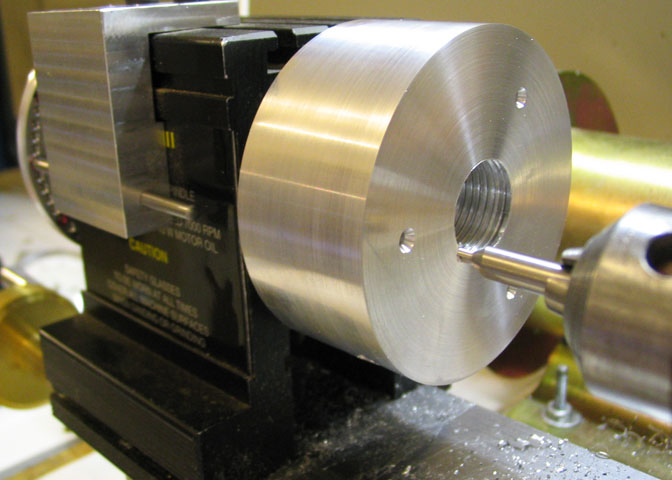
Here it is, mounted up on the face plate, and that mounted up on the spindle. This is all
the stock Taig lathe will swing without a head stock riser. That's all there is, 'n there ain't
no more...
Yeah. This is going to take a while.
Did I mention I should have bought a piece of proper round stock, cut to length?
(Well, no one in town had one, and I didn't want to wait for a custom cut house).
That place where the torch was started when this piece was cut out is a problem.
Interrupted cuts are hard on little cutters.
The best thing for this piece would probably be a leaded CRS, like 12L14. It cuts
great on small machines. So does cast iron, but I don't like cutting it. It just seems
to go all over the place. The piece I'm using is plain old A36 plate, (mild steel). It
doesn't cut as well as most other metals commonly used for turning. It will take a
smooth finish with a very sharp tool, but it's particular about speed and feed rates.
There is going to be a lot of swarf, since the work piece is over 4 3/8" in diameter,
and 1 3/8" thick. The finished piece will be slightly less than 4" dia., and 3/4" thick.
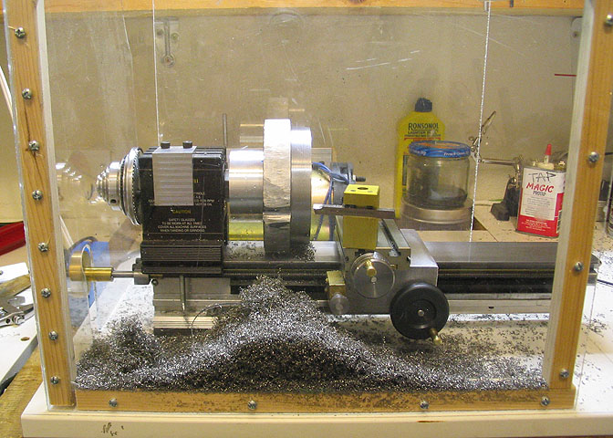
I made this small enclosure to cover the lathe and limit the amount of chips flying
around my shop room. It is completely open on the right side, so I can reach in and
turn the carriage and cross slide dials.
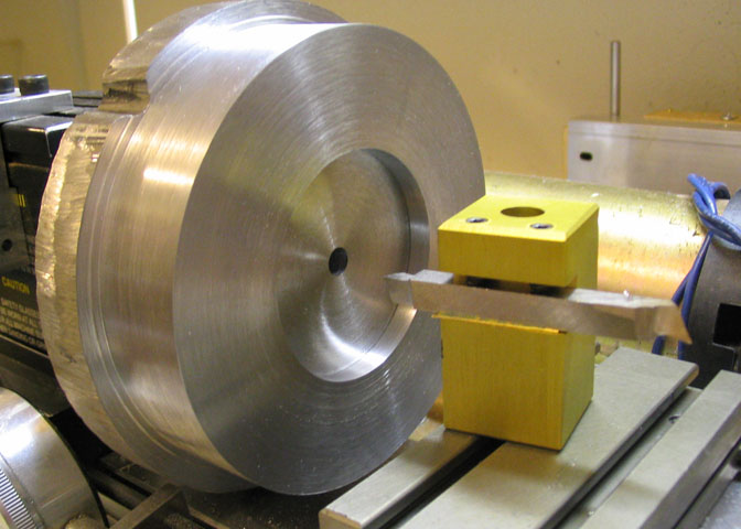
Since the cross slide will not go under the work piece, a HSS bit is ground with it's
cutting edge on the right side of the cutter. It's mounted in the tool post as shown in
the above photo, and little bites are taken at the work piece.
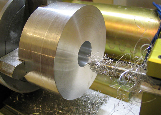
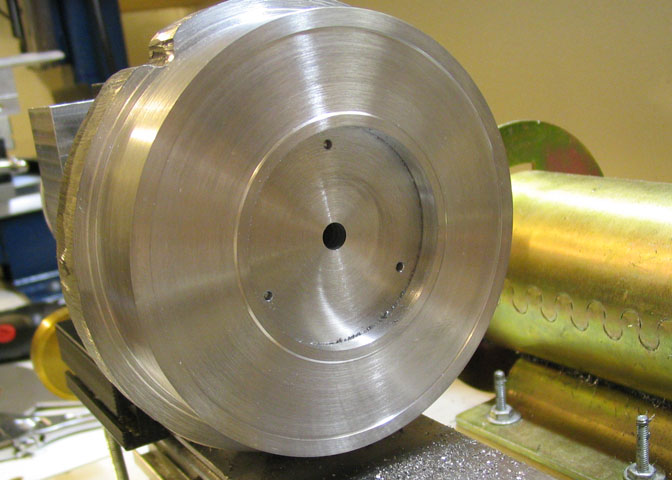
After turning down the piece to near the proper diameter for a length of about 7/8", a
sub 1/4" hole is drilled through the center and reamed .250". This hole will be used for
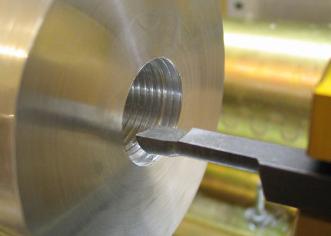
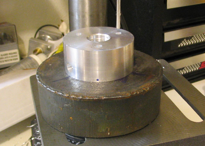
alignment later on. Then the recess for the mounting hub is bored, .250" deep and 1.950" dia.
After the recess is bored, a tool with a slight hook is ground to clean up the bottom surface.
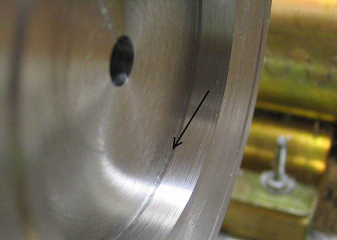
The purpose of the hook in the tool mentioned in the previous sentence is to cut out
just a bit of the corner of the recess to make sure the mounting hub fits into the recess
without hitting any unseen radius. See the arrow in the photo above.
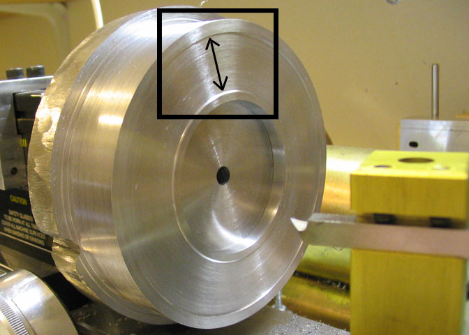
A shallow recess is cut to form two mating surfaces on the bottom of the table.
This recess only needs to be about .015" deep, and it's really not a critical dimension.
Leave a mating rim at the inner and outer diameters of the bottom of the rotating table.
The inner rim is 1/8" wide. The outer is 3/16". These two rims will mate with the top of
the base of the table.
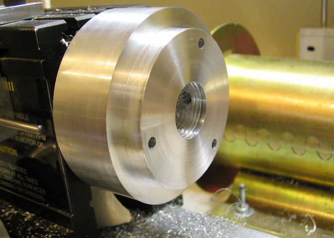
Now, since the work piece needs to be flipped end for end, three mounting holes are
spotted in the same manner as was done for the other side of the piece. The holes are
drilled 1/4" deep and tapped to the bottom for a 6-32 thread. The hole circle is 1.620".
The face plate has to be modified to fit the recess in the bottom of the rotating table.
The work piece is removed, and the face plate screwed back onto the lathe spindle,
and a section is turned on the end of it that will match the recess that has been cut
into the table work piece.
Since the holes in the face plate were drilled to the specs for the mounting hub, it
will match up perfectly with the holes just drilled and tapped into the recess in the
bottom of the rotating table.
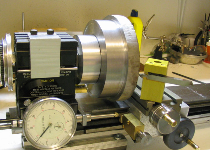
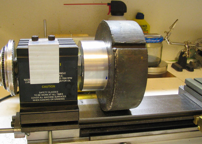
Everything is mounted up same as for the first side of the work piece, and it's time
to make a bunch more swarf. The big ugly chunk on the end just has to be turned
away, and what is left will be the makings of the rotating part of a rotary table.
Now, if you start off with a work piece that is already the correct diameter, you will have
a lot less cutting ahead of you. The piece will still have to be somewhat over length in
order to avoid having mounting holes in both sides of it, (the first mounting holes will be
machined away when the piece is brought to length). There will be a lot less cutting though,
if the diameter of the piece isn't 3/8" too large to begin with.... This is a big job for the Taig lathe.
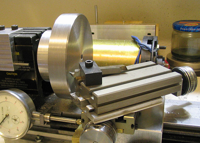
The last thing (for now) is to put a small bevel on the edge of the table. I'm still trying to decide
if I want to put two or three locating rings on the table's face. It can wait, for now.
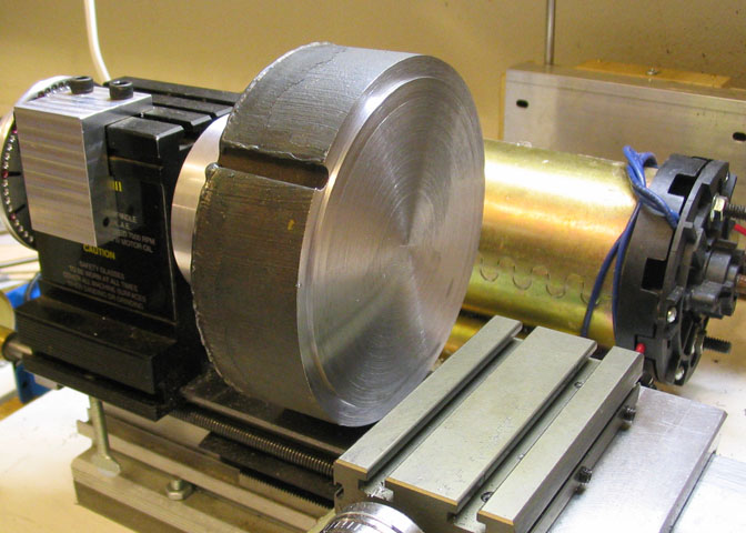
Finally, something round and smooth is carved out of the original piece. Much work
yet to do, but this is the single part that takes the most time.
Time to hit the link to Part Two.
Part Two
Part Three
Part Four
Part Five
More Taig Lathe & Mill Projects
deansphotographica.com
(home page)
Copyright Dean Williams