Building the Tripod Steam Plant
Miniature Steam Engine and Boiler
Part 4
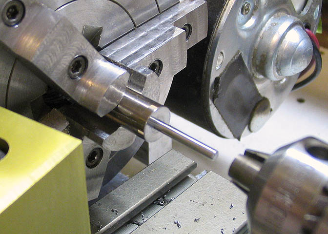
Next up is the crankshaft. Starting with the correct sized steel rod, a hole is drilled in the center of
the crank disc that is .001" smaller than the diameter of the crank shaft itself. Then the shaft is
held in the tailstock chuck and pressed into the crank disc.
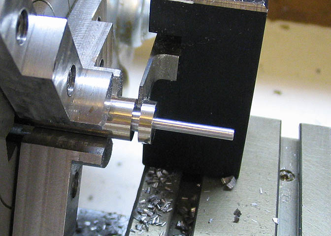
Now the disc and shaft assembly are parted off to a couple thou over the finish thickness. Then the piece
is held by the shaft end and the face of the disc is cleaned up to remove the few ridges left by parting.
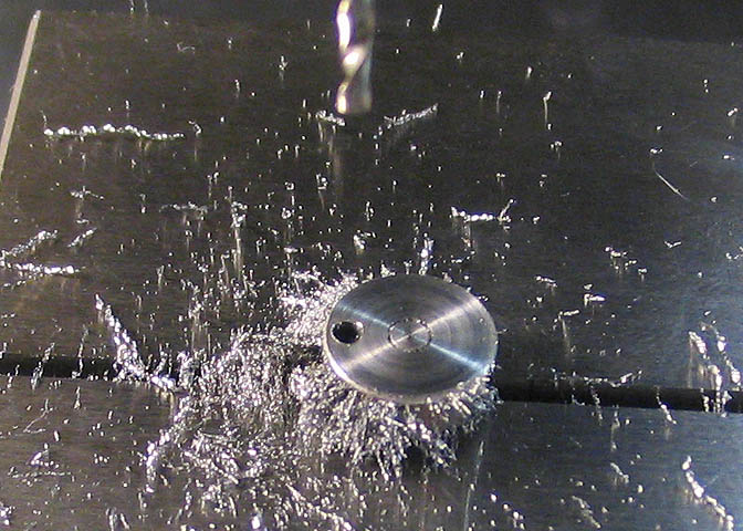
The piece is then moved to the mill and centered, then offset 1/2 the stroke of the engine and drilled
for the crank pin, again .001" undersized. The crank pin is then held in the mill spindle and pressed
into the crank disc and finally...
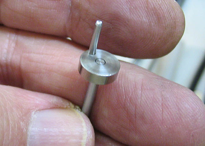
...the completed crankshaft. By using the lathe and mill to press the shaft and pin into the disc
at the time the holes were drilled, it assures the two are perpendicular to the disc, and parallel
to each other, which is what is needed.
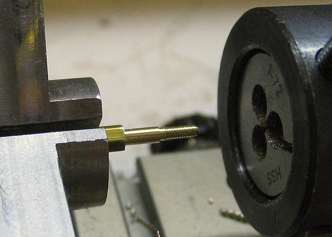
I had to make the screws that hold the cylinder springs, which hold the cylinder flat against the
engine standard. These are made from hex stock turned down to a couple of stepped diameters. One
diameter is to take the #1-72 threads, and the larger diameter is sized close to the ID of the cylinder
springs. The threads are cut with a split die, opened up at first to avoid breaking off the thread
shank, then closed down a bit to bring the threads to size.
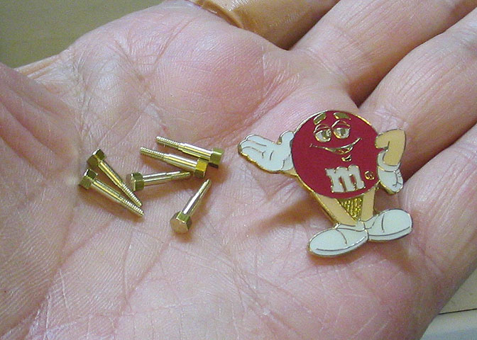
That's them. Six little cap screws.
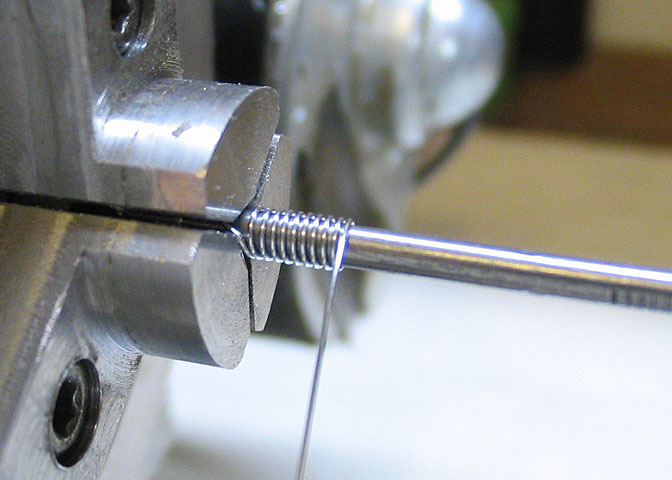
The springs had to be made, since they are quite small and I didn't hold much hope for finding them
in a commercial size. These were made using a small nail for a mandrel, and .013" dia music wire.
The music wire in this case is polished guitar string.
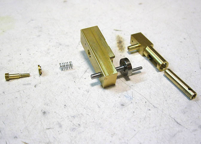
Here's an assembly shot of the engine parts, minus the flywheel. Another little part I didn't show
being made is the small stepped washer seen between the cap screw and spring. The minor diameter on
this washer fits inside the spring and the screw goes through the works and into the cylinder pivot.
The step on the washer and the counterbore in the standard prevent the spring from bulging sideways.
The Flywheels
With all of the other parts for the boilers and engines made, it's time to turn to the flywheels. These
will be 1" diameter, and hopefully, some kind of nice shape.
Starting with brass round stock, I parted off eight round blanks. There are only six engines, but for
what is planned, I figure there may be a couple of goofs destined for the scrap bin.
I have full round soft jaws on the chuck, here. The jaws are made to be cut up for whatever diameter is
needed, and to provide a large clamping surface for thin work pieces. These are made for my particular
brand of lathe, and since they are considered a consumable, are pretty cheap. They are $8 a set, and
after you've cut them up enough to be un-usable they get tossed and a new set put on. I've gone through
a few sets of these.
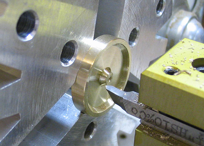
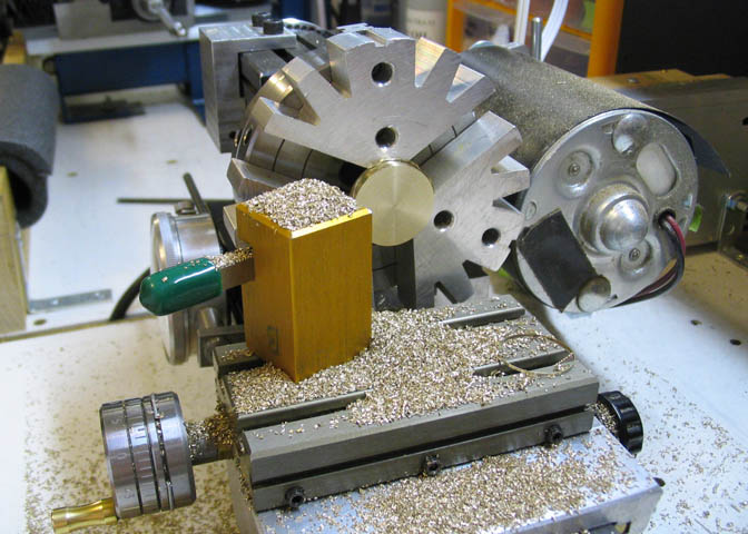
A tool bit is ground up so that the bevel on the flywheel hub and the inside of the rim can be cut
without changing tools. Notice that the part of the tool bit under the cutting edges slopes away
under the front of the tool. Since the tool is plunged into the work for these cuts, that is needed
to prevent the lower part of the tool from rubbing on the inner radius of the flywheel rim.
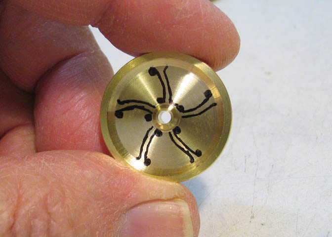
I wanted to make something other than a flat wheel or a disc with holes, so I did some doodling on
one of the blanks to come up with a shape. Spokes would be nice. Curved spokes would be nicer.
After finding a radius that looked okay for the curve of the spokes, I got out some of my old drafting
tools and scratched up some arcs and centers to get some dimensions and locations for off center
mounting of the pieces on my rotary table.
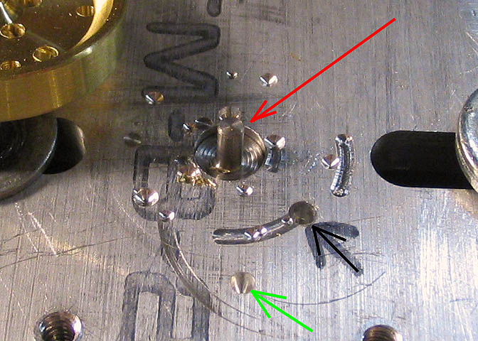
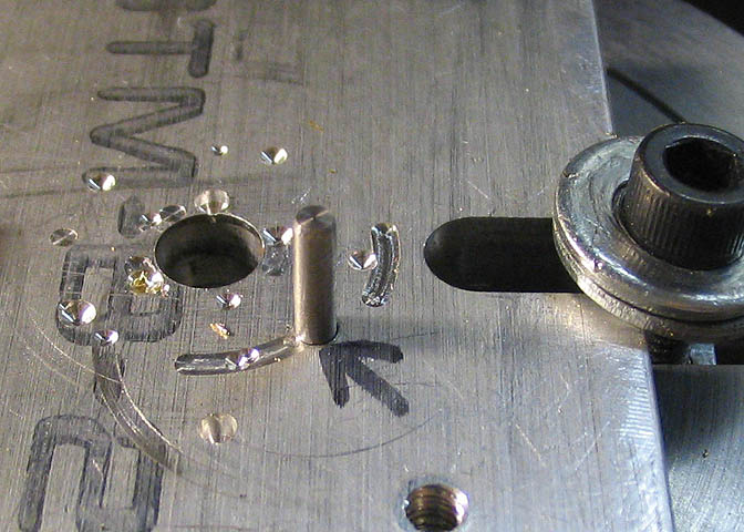
The rotary table is mounted and centered under the spindle on the milling machine, then a sacrificial piece
of aluminum plate is mounted directly over the center of the RT. This aluminum plate has three holes
drilled for locating various features of the spoked flywheels. The hole at the red arrow has a pin in it
that will fit the center bore of the flywheel. That pin, and the center of the RT run true under the mill
spindle, and will allow drilling hole circles that run concentric with the rim of the flywheel.
The hole at the black arrow is an offset, and when the flywheel is placed over a pin in that hole it lets
the RT rotate the flywheel in a way that allows cutting one side of the spokes.
The hole at the green arrow is to align the flywheel blank for cutting the spoke shape. It aids in indexing
the blank to the correct position so the spokes are equally spaced and the same thickness. That hole is
just a guide, and is only used to help space the spokes.
The other holes and marks on the plate are a result of using it and cutting a little too deep while drilling
or milling the features of the flywheels. Besides its use as a jig, the plate also protects the top of my
rotary table.
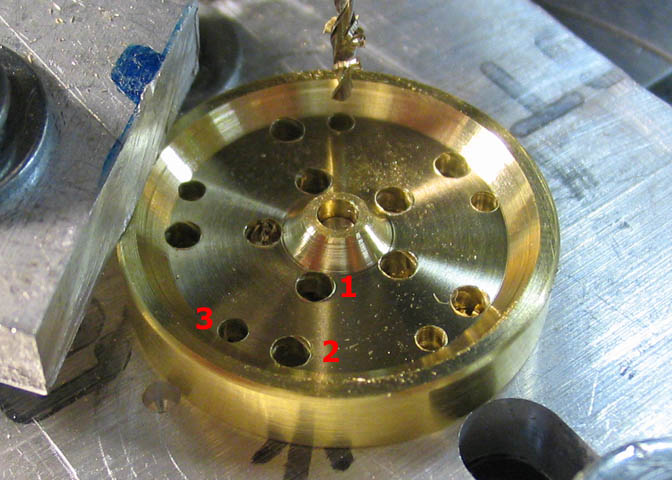
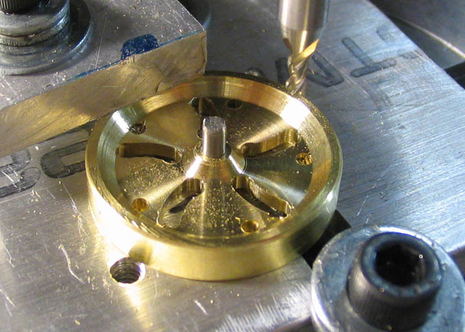
This picture shows the process of drilling all the locating holes in a flywheel blank. The holes in the #1
position are drilled first. Then the holes at the #2 position, and then the #3 holes. The #1 and #2 holes
are 5/64" diameter and are the positions of the front side of the spokes. The #3 holes are 1/16" dia.
They are the position of the back sides of the spokes. All of these holes are located in concentric circles
off the center of the flywheel.
The number 1 and 2 holes are drilled at 72 degrees apart. After the last #2 hole is drilled, the RT is
turned 22 degrees and then the smaller #3 holes are all done 72 degrees apart.
With all those hole circles done, the pin is pulled from the center hole and another pin put in the offset
hole at the black arrow.
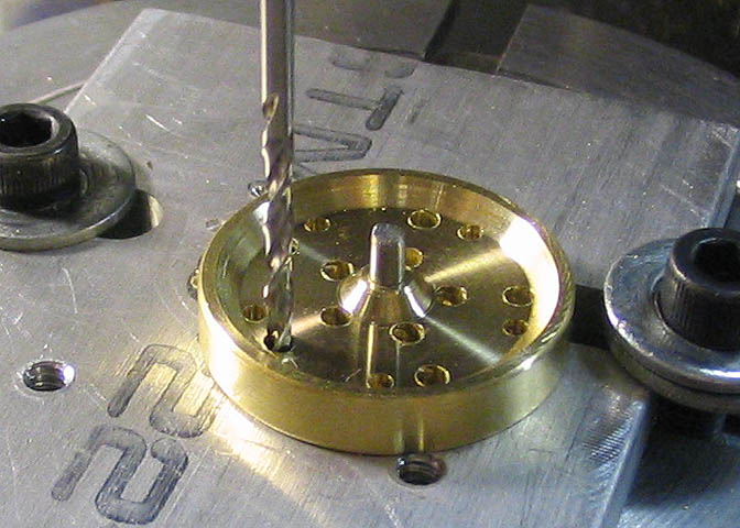
The blank is placed over that pin, and a drill bit is used to position the blank for the next step, then
the blank is clamped down on the RT. (I just hold the drill bit with my fingers.) The mill table, (not
the rotary table) is repositioned so that when the RT turns it will cut an arc from the outside rim to
the inside hub between holes 1 and 2.
Now the first arc is cut using the #1 and #2 holes as starting and stopping points. These are all
cut with a 5/64" diameter end mill
This shot shows the first set of arcs completed.
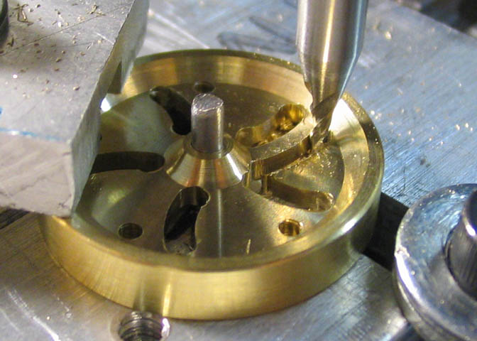
Now the second set of arcs can be cut. The blank remains on the offset pin in the plate on the RT,
and the mill table is repositioned again to put it in the correct position to cut the next set of arcs.
These cuts are done with a 1/16" end mill. After each arc is cut, the clamp on the blank is loosened
and the blank rotated so the next starter hole is lined up with the end mill.
Throughout all of the cutting on the piece, the rotary table remains clamped to the milling machine
cross slide table in the same position. The only axes on the milling machine that change are the
mill table itself, and the rotating part of the rotary table. Hope that makes sense.
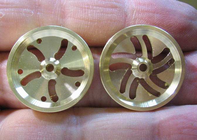
This shot shows a blank with the first set of arcs cut compared to one with both sets of arcs done.
It doesn't take much imagination to see what has to be done next.
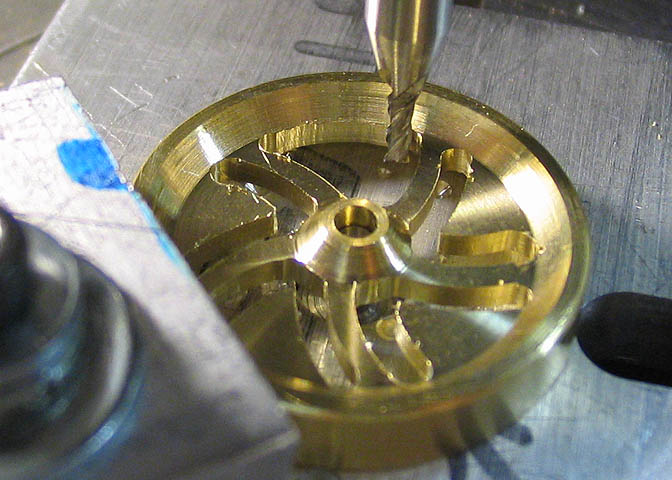
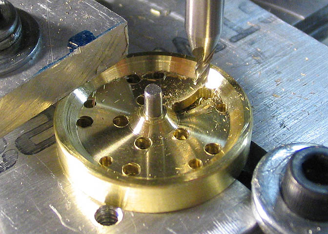
Now the RT is once again centered under the milling machine spindle and the blank replaced on the original
pin that was used to drill all the holes in the earlier steps. Then, by offsetting the mill table to the
original diameters of the hole circles, the waste between the spokes at the hub diameter, then the rim
diameter can be cut away.
In this shot the inside rim looks pretty ragged. I'm just roughing out the waste pieces here.
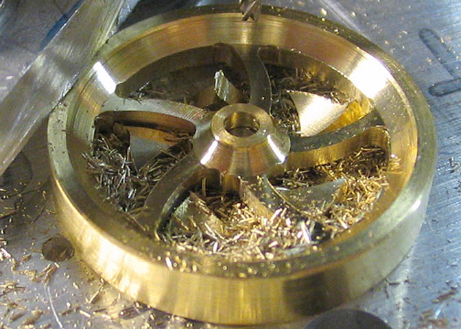
Final steps are to increase the diameter of the cuts to the rim a few thousandths of an inch to clean up
the rough edges, giving a smoother finish. I start these finishing cuts somewhat inside the final inside
diameter of the rim and work outward until the end mill cleans up the small original drill bit holes.
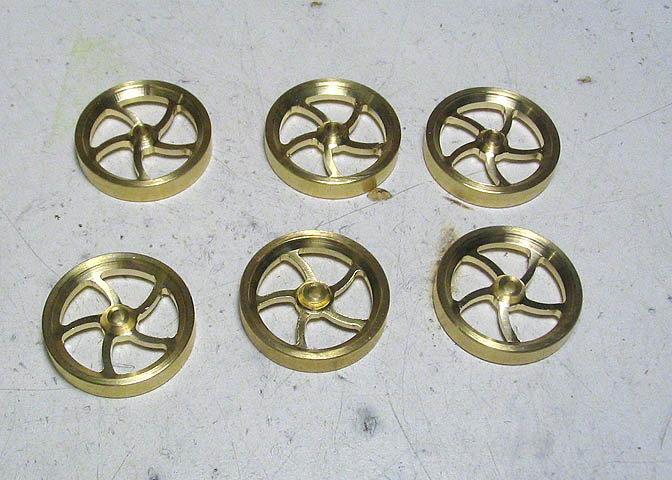
I ended up with six good flywheels. If you remember, I started with eight blanks. On one of them I got
to cranking the RT a little too causally and one of the spokes is slightly mis-cut. The eighth blank did
not get used at all. I'll save it for another day.
All that's left is to test run all of the engines, do a little finish work to shine up the finish of the
brass parts that still have some of the discoloration that comes from the foundry, and pressure tests.
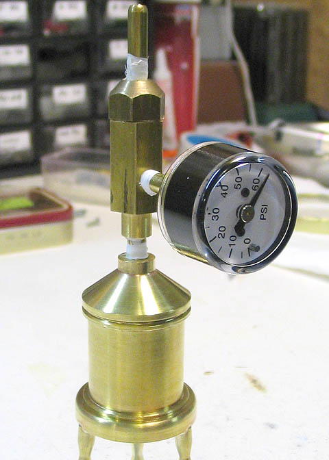
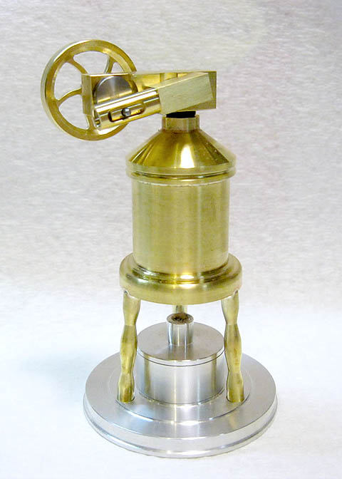
All of the boilers get hydro-tested to 60 psi, which is shown in the picture above. A hydro-test is a
safe way to test boiler shells, as it will not produce any shrapnel in the case of a boiler failure. Should
a boiler fail under hydro-test, all that will happen is a quick squirt of water will come out at the point
of the failure. The boiler may be ruined, but the surroundings, (mainly, the people), will get nothing
more that a bit wet.
To test these boilers, they are first filled completely full with water. No air space is left at all. Then
the pressure adapter is screwed in the top and more water is forced in until the gauge reads what you want
for the test pressure. That is 60 pounds here, and the boiler is then left for a time interval, such as
a half hour or so. If the pressure remains constant over the time period, the boiler is sound. If it goes
down, you have a leak somewhere.
It is fairly important to keep the boiler full of water at a constant temperature throughout the test period.
If the boiler gets warmer or cooler during that period, you can have a false test. I start with both the
boiler and the water at room temperature, and keep the boiler at that throughout the test. That is fairly
easy to do indoors, since it is not likely that the room will change temperature enough to affect things.
If the temperature goes down a few degrees, the test will give the impression that you have a leak, since
the pressure will go down.
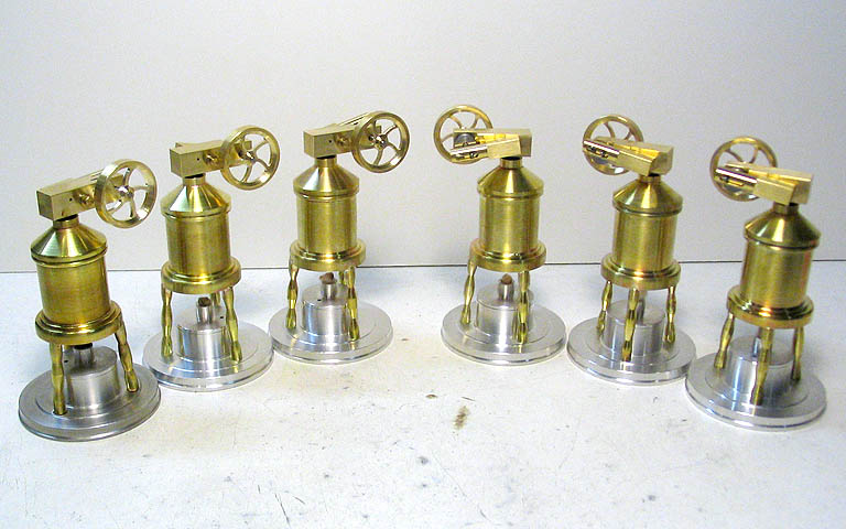
Here they are, all boilers pressure tested and all engines test run.
Below is a video of one of the running Tripod Steam Plants.
Thanks a lot for having a look!
Go to:
Part 1
Part 2
Part 3
Part 4
To go back to the main projects page, click the link below.
More Taig Lathe & Mill Projects
Copyright 1998-2012 Dean Williams