Building the Tripod Steam Plant
Miniature Steam Engine and Boiler
Part 3
Engine Work
I start the engines with the standard. This is the piece that holds all of the other engine parts together.
Beginning with a 3/8" square brass piece cut to length, a recess is milled in the end where the crank disc
will sit, and then the hole for the crankshaft is drilled and reamed.
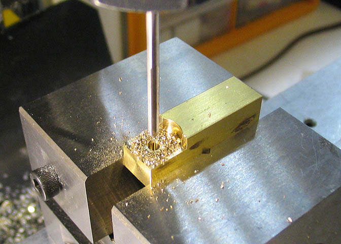
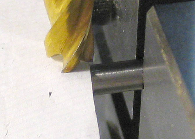
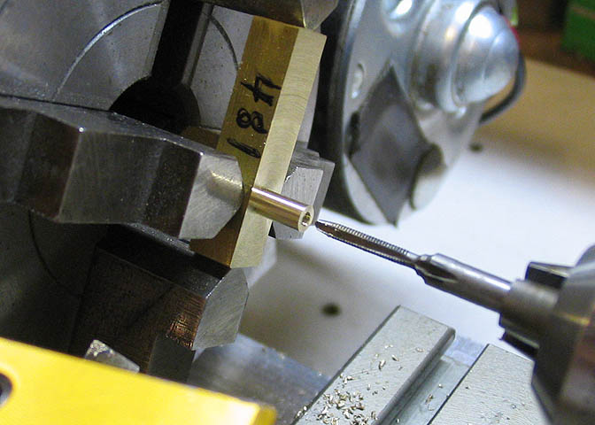
Moving down the piece, the hole for the cylinder pivot is reamed, then a shallow recess is milled over that
hole. The recess at that point is to reduce friction and to help the cylinder sit truly flat against the
standard piece. Finally, the steam ports are drilled, shown above.
Each of the holes drilled or reamed on this piece are located by using coordinates dialed in on the milling
machine dials.
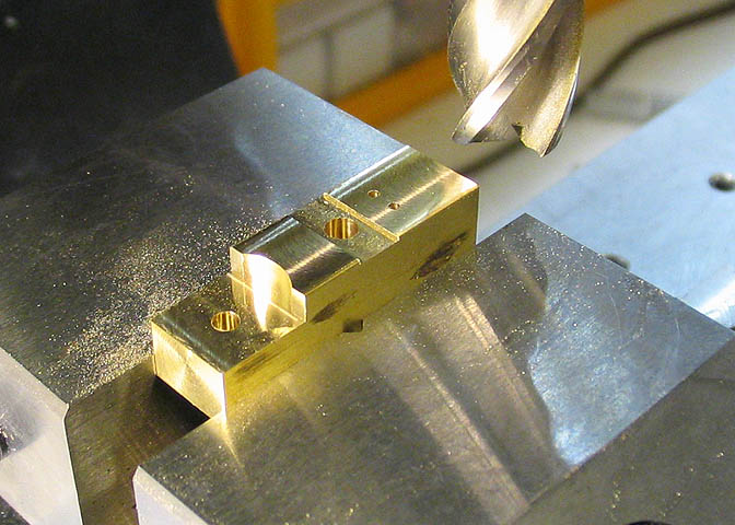
The last step on this side of the piece is to take a skim cut of about .002" with an end mill. This assures
that the mating surface for the cylinder is perpendicular to holes just drilled. This step is done without
having disturbed the work piece from its setup for drilling all the holes.
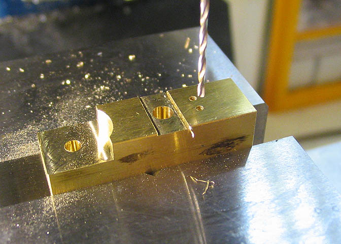
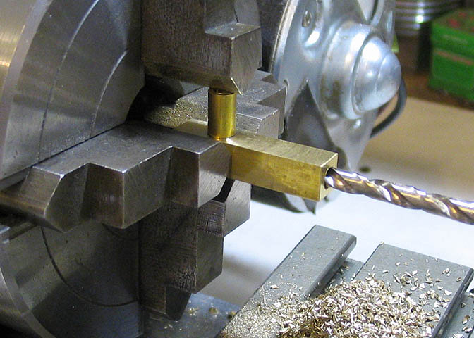
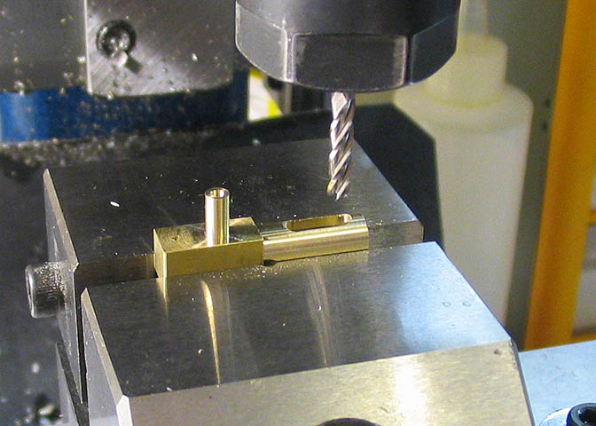
The piece is now turned on it's side and the hole for the steam admission pipe is milled in until it cuts into
the tiny steam port intake hole. The milled hole is slightly smaller than the steam pipe for the engine.
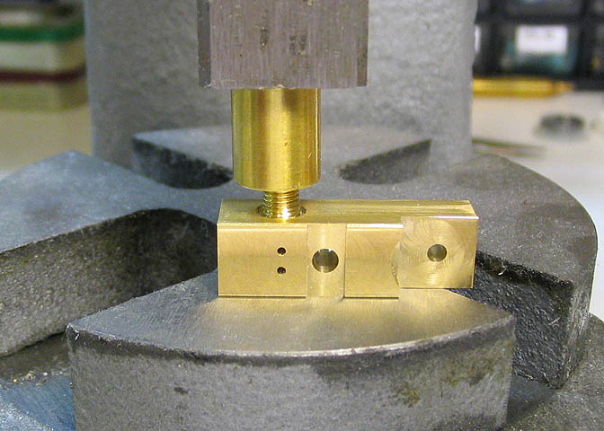
Some 3/16" steam pipe is cut and threaded for the same thread that is in the top of the boiler, and the
pipes are pressed into the admission hole. The press interference is .001".
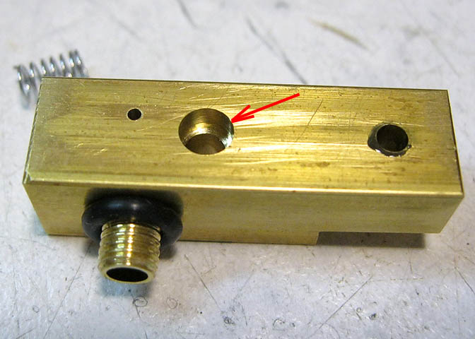
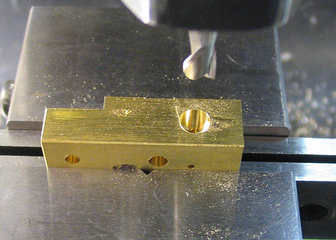
This pic is out of sequence, but one more thing done on the standard is to counterbore a small recess
into the back side of the pivot bearing hole. This counterbore fits the cylinder spring.
The cylinders will be made next. They will have a bore of 5/32", and a drilled hole is not good enough, IMO.
The cylinder bore should be reamed. I recently dulled my 5/32" chucking reamer, and haven't replaced it yet,
so I need to make a shop reamer to do this job.
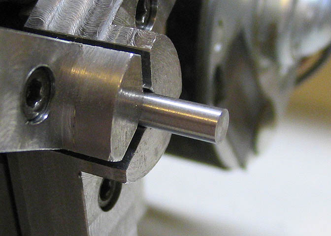
What I'll show here is called a "D bit" or "D reamer", depending on who's telling the story. Starting with
a piece of 5/32" drill rod, one end is faced off smooth.
Next, a small 45 deg bevel is put on the end. This can be cut with the compound slide on the lathe, or simply
put on using a fairly fine (and sharp) file. How large you make the bevel on the end of the piece depends on
the diameter of the tool you are making, and how large you can drill the pilot hole that this tool is expected
to ream out. The bevel is needed so the tool can get started in the pilot hole. You'll see more about this
later, and things will become clear. For the moment, just trust me that it needs a bevel on the end.
Now the piece is taken to the mill. This step is going to put the cutting edge on the D-bit. The depth of this
cut should be fairly accurate. To set the end mill so I know that it will cut the proper depth, I use a piece
of cigarette paper, and with the mill motor off, lower the end mill until it just starts to pinch the ciggy paper
between it and the drill rod, then set the dial on the machine to zero.
The machine is then started and half the piece of drill rod is milled away. The length of the cut is generally
equal to the diameter of the piece of drill rod. In this case, the drill rod is 5/32", so the length of the cut
should be about 5/32", and the depth of the part milled away is .078", i.e. one half of 5/32".
The way I've explained it works well for me. Some guys say go down half the diameter, plus .001", some say to
go down half the diameter, minus .001". I used to worry about that until I found I couldn't tell the difference
in the way the tool works how ever you do it, so now I just go half and call it good.
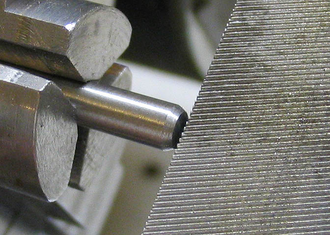
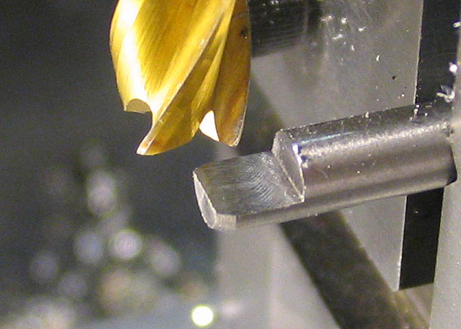
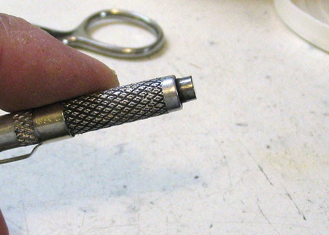
Looking at the picture above, I think you can see the need for the bevel. This tool is made to go into an
existing hole, but one that is slightly smaller in diameter than the tool itself. The bevel acts as a guide
so the tool goes into the hole straight, and gives it a way to start into the hole in the first place. Without
it, the tool would tend to just butt up against the edge of the existing hole that you want to ream out.
Before this next bit, here are a few terms regarding heat treating metals;
The first is "Annealed". That means to heat the metal to a temperature that will return it to its softest
normal state. For instance, a file is probably the hardest thing in a workshop, excepting high speed steel
and the carbides. You can cut most any regular steel with a file. You could make that file quite soft
by annealing it at a certain temperature, and letting it cool slowly.
The second term is "Hardened". With tool steels and some high carbon steel, if you heat it to it's non-
magnetic state, then quench it, it will become extremely hard. So hard that it will break to pieces if
you were to hit it with a hammer.
The third term is "Temper". This is also called "Draw" or "Drawing" by some older machinists and tool makers.
After hardening, carbon tool steel is tempered so it will not shatter in use. The tempering takes just a
touch of the hardness out of the steel and makes it tougher and more resistant to chipping and breakage.
There are different degrees of temper, and they depend on the intended use for the tool steel. For instance,
drill bits are tempered just a little bit, because they are expected to cut other steels, but they will
not take a large shock. A tool like a cold chisel or punch that you would use with a hammer is tempered
to a greater extent, since you are expected to beat on it, and if it was left too hard, it would break.
The shop reamer now needs to be hardened. This particular drill rod is called "water hardening". That means it
will harden when heated and quenched in water. There are a few others, mainly, "oil hardening", which, as
you may guess, hardens in oil. There are other types too, but these are the ones I mainly use. Water
hardening works fine for most tool-making.
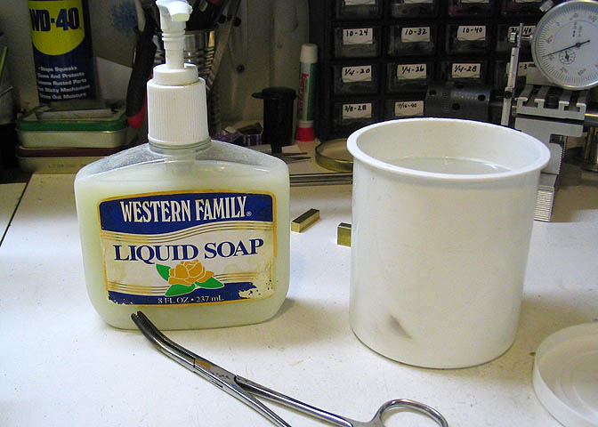
For hardening, I use a little soap, a container of water, about body temperature, and something to hold the
piece so you don't burn your fingers.
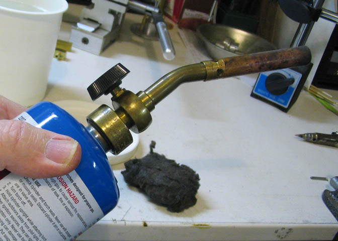
You need a torch of some sort. Must produce enough heat to get the drill rod red hot, the color of cooked
carrots. The little fist sized butane torches won't cut it. The one in the picture above is a typical plumber's
type Bernzomatic torch made for 14 or 16 ounce propane cylinders. This will do fine for hardening up to
about 1/2" diameter drill rod.
If you are not familiar with the various colors of heated metals, a small magnet will come in handy.
Here we go;
The soap is to help keep the piece of drill rod from turning black and crusty when you heat it. You don't have
to use it, but it makes the job easier. Put a drop of the soap on your finger and rub it on the surface of the
metal that you are going to heat.
Light the torch and turn it on full blast. Using the tongs or pliers, hole the drill rod tool by the end
opposite the end you want to harden. Hold the tool in the torch flame, turning it to heat the end evenly.
Watch the very end, where the cutting part is. You will see it go through a number of colors. The color you
are looking for is kind of a bright carrot orange. If you have trouble recognizing that color as it comes
up, use the magnet. When the tool looks about right, bring the magnet into the flame and see if the tool is
attracted to it. There is a certain temperature that tool steel will no longer be attracted to a magnet, and
that temp happens to be just about the right heat for hardening drill rod. So, if you don't know the exact
color to be looking for while heating your piece, the magnet trick will help you out.
When the tool reaches that temperature, leave it in the flame for a half minute or so, maintaining that color,
then dunk it directly into the water, end first, straight in, and swirl it around until it's cool. Do this
dunking fast. It must still be the proper color when it enters the water. Have some conviction! Do not lay
it in the water long ways. That will cause it to warp. Plunge it straight in as if you were dropping a long
piece of wood down a well. Don't forget to swirl it around or it won't harden properly.
At this point, the end that you heated will be as hard as it will ever get. If you are using it on brass or
aluminum, it will -probably- be okay to leave like this. The tool is called "dead hard" at this point, and
it is rather brittle. If you need to use it for a number of projects, or on harder metals like steel, you will
have to temper it, or it won't last.
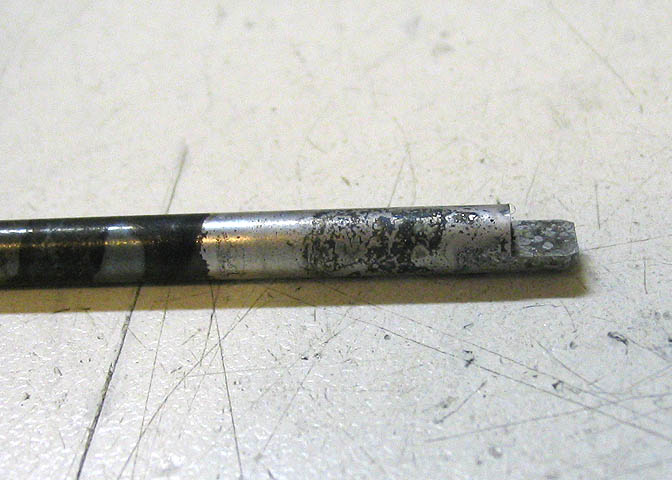
Here's the tool as it came out of the water. It's dead hard, here. Since I'm going to use it a number of times
for this project, and I'll probably use it on steel some time in the future, I'll temper it.
You can see where the soap was where it's mainly white metal with some black swirly marks. To the left of that,
you can see where there was no soap, and it's turned black. That black stuff takes a little rubbing to get off,
while the swirly stuff in the white metal comes right off. To temper the piece, it needs to be shined up a little
bit, so I will be able to see the colors of the metal again as I re-heat it. Using steel wool, it cleans up shiny
in a few minutes.
To temper after hardening, the metal has to be heated again, but not to red hot like last time. Just until the
metal turns a color that the charts call "straw", which is actually a yellowish-gold. That color comes up very
fast, and you have to watch it closely. As soon as it reaches that color on the cutting edge, dunk it again to
cool it.
A less chancey way to temper is to use an oven. For small pieces like this, the kitchen oven will do. Set the oven
to about 375 deg F and put the piece in for a half hour. If you do it this way, you don't have to dunk it, because
there is no worry about it getting too hot. When I'm in a hurry, I do this step in the flame of a torch, and I'm
pretty well acquainted with the proper tempering colors. If I have time to make up a cutting tool ahead of time,
I use my toaster oven for the tempering step.
After these heat treating steps, the tool will be hard and tough at the same time. All that is left is to hone
it lightly on a GOOD very hard, smooth arkansas stone. Hold the flat part of the cutting end, that is, the part that
was cut with the end mill when making the tool, against the arkansas stone and push it in one direction.
Pick it up off the stone, return to the starting point, and again, push it along the length of the stone. Two
or three strokes like this will remove the "feathers" left from machining the piece in the first place, and will
make the cutting edge of the tool very keen and sharp.
So, enough of that. Half of you are probably asleep by now, and the other half have gone to bed.
Now that I have a tool made to cut the cylinder bores, I can go on the the cylinders themselves.
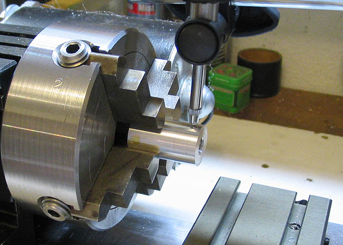
The cylinder is a rectangular piece of brass with a proper pivot bearing. I need to locate where that bearing
goes on the piece. It is 5/16" from one end of the brass cylinder, so to get the four jaw chuck setup quickly
for that dimension, I put a piece of 5/8" rod in the chuck and clocked it in true.
I pick one jaw of the chuck, #3, that I will not touch during this exercise. All of the jaws on the chuck are
at 5/16" from the center line of the lathe at this point, since the 5/8" rod is centered in them, (half of 5/8"
is 5/16").
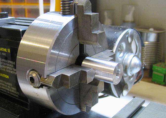
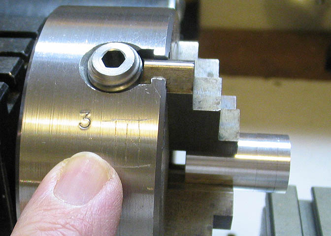
Now the number 3 jaw is turned down to the bottom, and remember, I'm not going to move that jaw. The other
jaws are opened up a bit so I can fit the piece into the chuck.
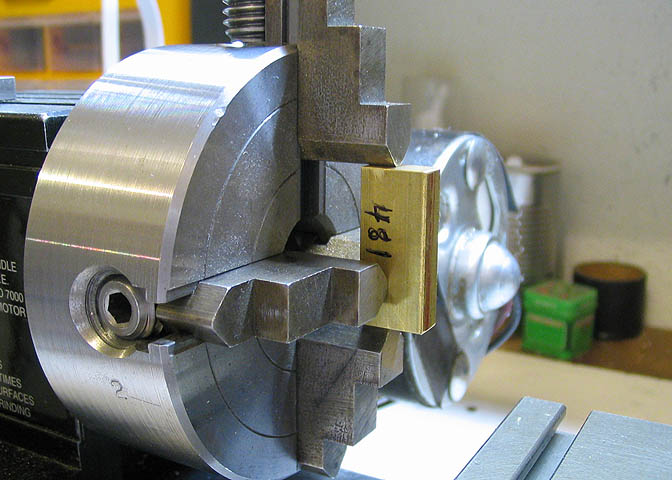
The cylinder piece is placed against the #3 jaw that is facing down, (the bottom jaw), and the top jaw is screwed
down just enough to hold it.
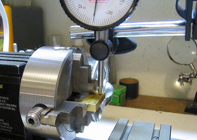
Finally, the sides of the piece are dialed in to zero, and jaws 1, 2, and 4 are tightened on the piece.
Now I can cut the pivot pin on the cylinder and know it will be exactly where I want it.
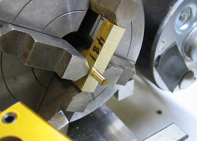
Without moving the piece in the chuck, the pivot pin is drilled and tapped for the pivot screw, and this
step is done.
The piece is now oriented with the end that will be the bore facing out, and centered in the chuck. The
pivot pin that was cut earlier is protected by a piece of brass tubing, so the chuck jaw will not
damage or deform it.
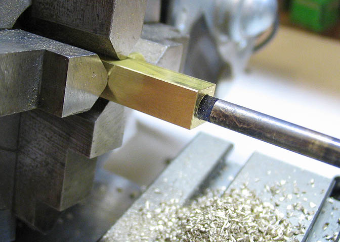
The D-reamer made earlier now comes into play. The bore is first drilled .010" undersized so the walls of
the cylinder can be cleaned up to dimension by the reamer. In the picture, about half of the cutting end
of the reamer has entered the bore. It is fed in slowly to allow it to cut cleanly, and backed out to clear
the chips after each 1/4" of advancement into the hole. Unlike a store bought reamer, this one has no
flutes to carry away the chips, so has to be be withdrawn often and the chips blown out with a puff of air.
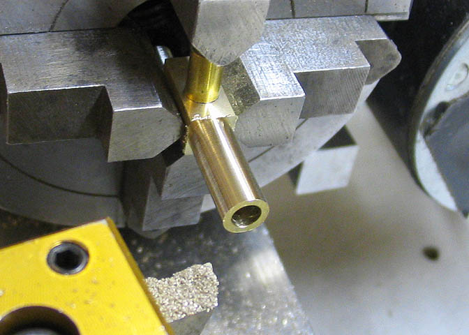
Last step on the lathe is to cut the end of the cylinder for the trunk guide. This trunk guide keeps the
piston very straight in the bore as the engine runs, and makes for a long lasting engine. Since the piston
is quite long and has no unsupported end like the con-rod on conventional wobblers, the trunk acts as a crosshead.
The remaining two ops are done on the milling machine. The piece is centered under the mill spindle and
the cylinder intake port drilled and slots for the trunk milled out. The slots allow the crank pin to reach
into the piston.
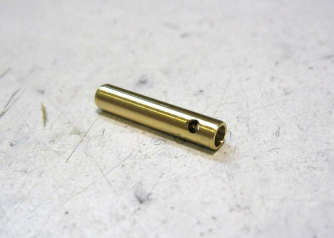
I didn't show making the pistons since they are just a simple round bit with a cross hole for the crank pin.
A single pic should do. The piston is hollow most of its length to reduce reciprocating mass. That makes
for a little bit less vibration.
Please Continue to Part 4
Go to:
Part 1
Part 2
Part 3
Part 4
To go back to the main projects page, click the link below.
More Taig Lathe & Mill Projects
Copyright 1998-2012 Dean Williams