Building the Tripod Steam Plant
Miniature Steam Engine and Boiler
Part 1
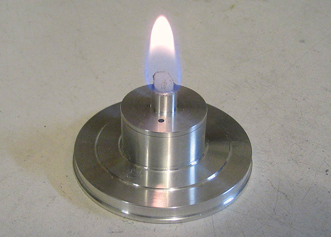
This is a small self contained steam plant with an integral engine perched on top of the boiler.
It's fired by an alcohol wick burner mounted in the base which produces steam in the boiler that
powers the small engine. The engine has a bore of 5/32" and stroke of 1/4" and runs a couple
thousand RPM when at full steam.
I didn't have any drawings for this when I started the project, and drew up the parts as I built.
A friend in England asked me to make one for him, and all he had was a picture of one he had
seen. Another friend in Denmark had one, and he was able to send me a number of figures to
use as a starting point so I could build a few. I ended up making six, keeping one and selling the rest.
The original design type comes from one of Dr. James Senft's creations called a Thimble Power Plant.
That one was somewhat smaller, and as the name implies uses a sewing thimble for the boiler.
Besides that, his engine unit alone was much smaller than the one that will be shown here. The
engine and boiler that will be shown here are based on his design, though the dimensions are far different.
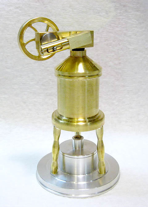
This will be a build article for the small unit pictured above. It's small enough for most any sized
lathe, the largest diameter being under 2.5". I used a Taig lathe and milling machine, along with
my small Atlas lathe for a some parts. With a little extra setup work and as long as you aren't in
a hurry, this could be done with just the Taig lathe and it's accessory milling attachment, or most
other small similarly equipped lathes I can think of, such as the Sherline, Unimat, Prazi, and etc.
Probably enough blabber on my part. So here we go..
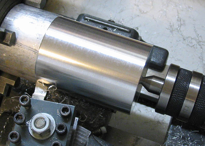
I started with the base, and will be making a run of six.
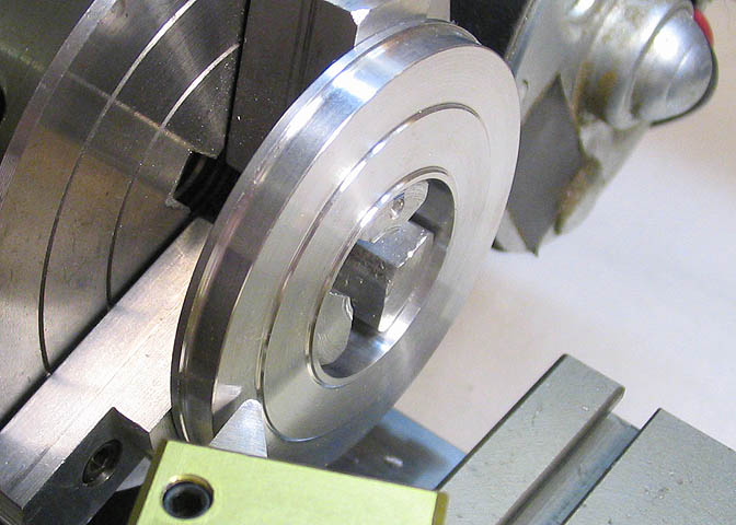
After skimming the outside of this piece of aluminum, I ran a parting tool into the side for the base pieces.
I didn't cut all the way through.
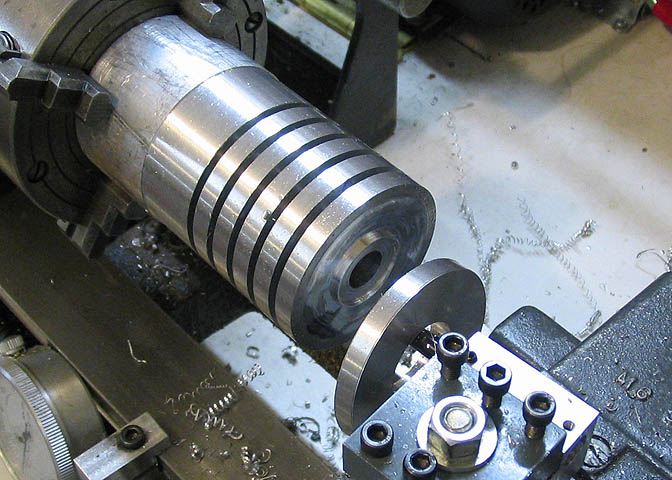
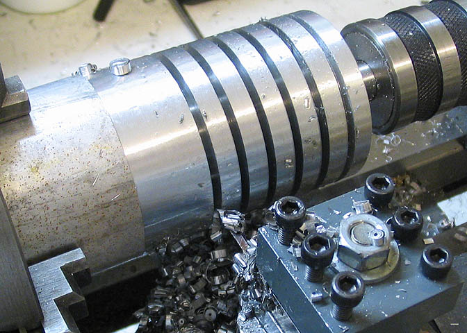
Then run a boring tool down the center, which drops off the individual base pieces as it bores. This saves
having to drill a center hole in each base piece later.
After the pieces are cut off, they are put in the lathe chuck and the profiles are cut. These are just to
dress up what would otherwise be a rather plain appearance.
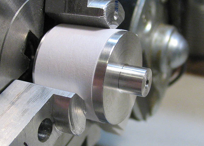
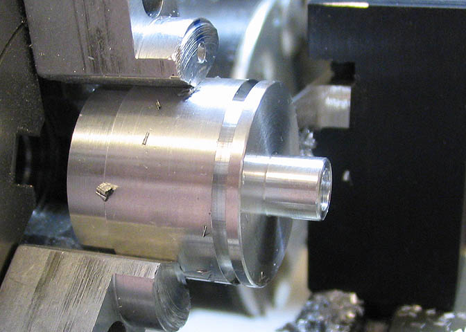
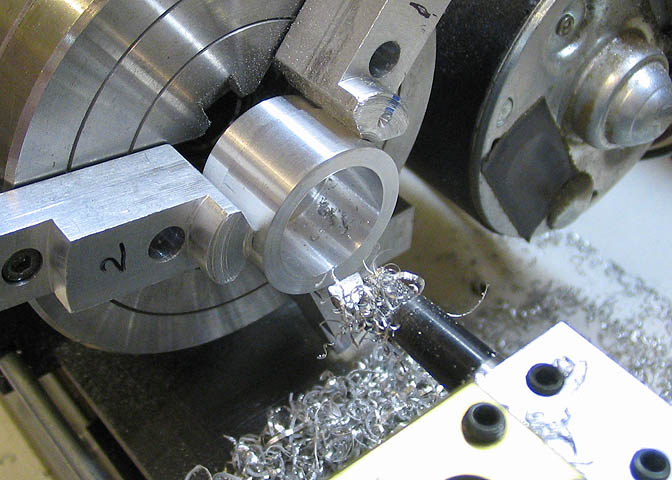
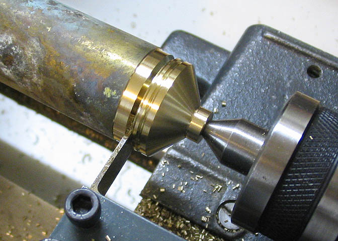
This will be a burner. I started by taking a skim cut on the OD of a piece of aluminum rod, then parting
off six pieces. The paper shown in the pic is to keep the chuck from marking the side of the piece as the
top part is turned for the wick.
Now the piece is turned around in the chuck and the bottom gets a smaller OD to fit into the base piece.
The end is drilled for the wick.
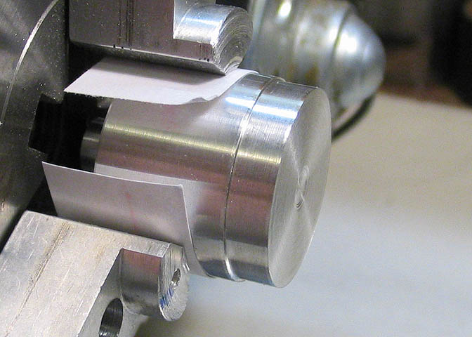
Now a parting tool is run in about 1/16" to make a lip for the lid of the burner.
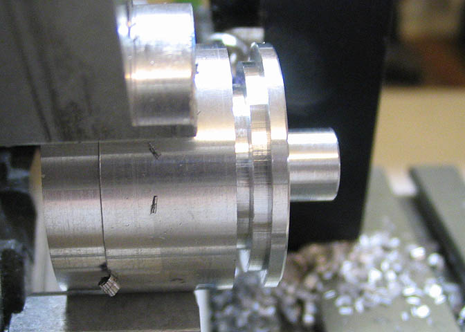
Then the parting tool is moved in toward the chuck another 1/16" and the top is parted off.
This leaves a nice ready made rim inside the burner lid.
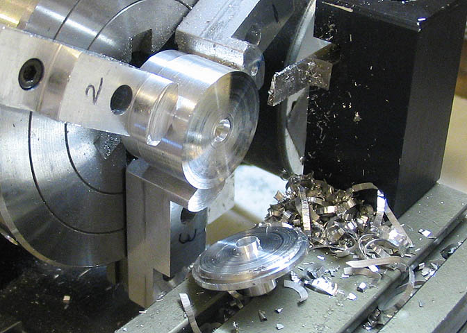
The top is complete as it comes off the parent stock. All that must be done is to clean up the feathers.
The inside can then be bored out to a diameter that fits the lip on the top piece.
One base finished.
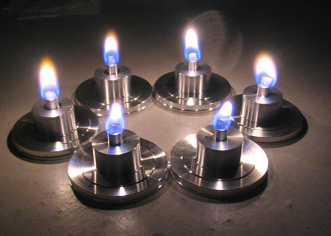
And the rest done and 'test fired'.
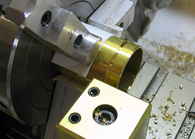
Time to start on the boiler tops. A little straight turning, a little bit of a taper, a groove, and
part it off.
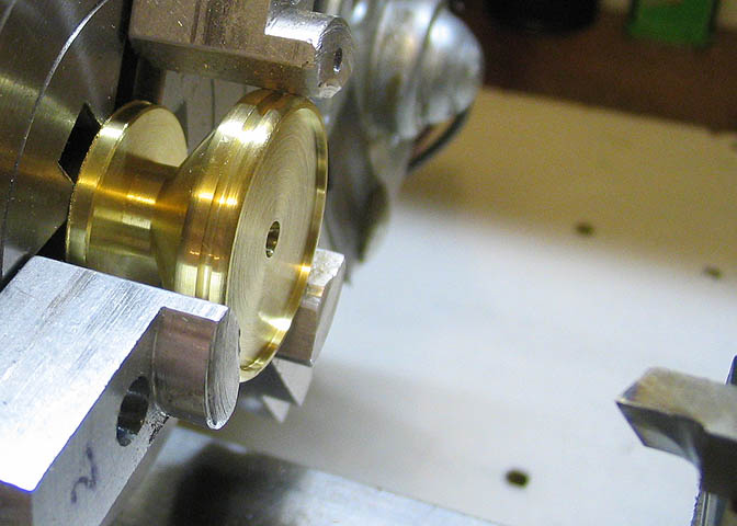
Each piece is counter-bored to accept the boiler shell. The piece shown inside the chuck is a plug
turned up to help in keeping the boiler top square in the chuck.
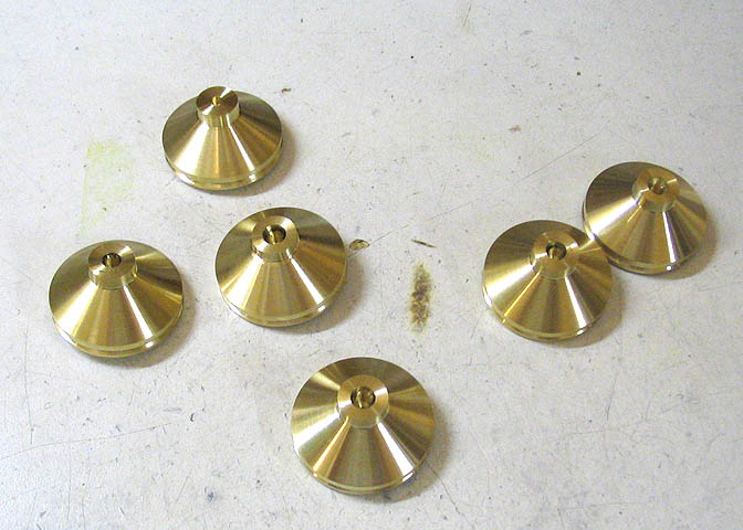
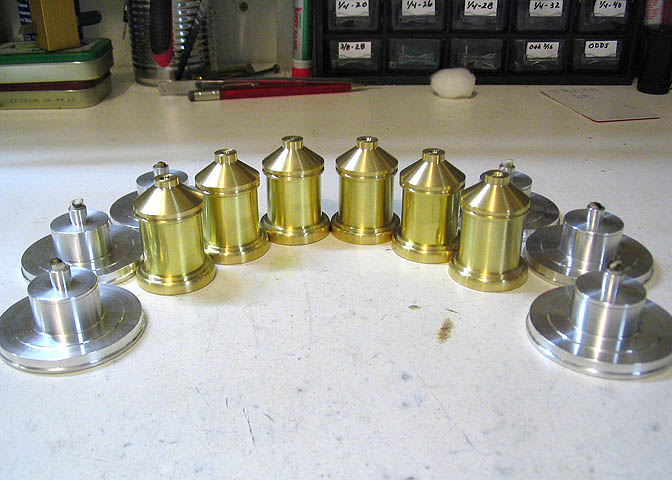
Six of them done.
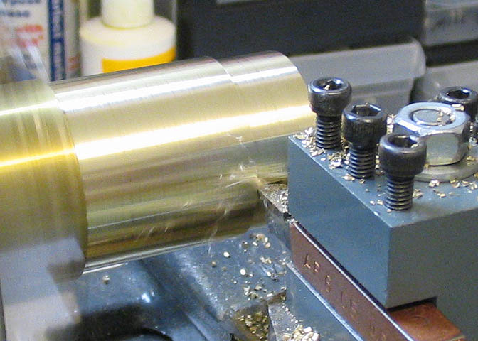
Turned down a nice fat piece of brass for the boiler bottoms.
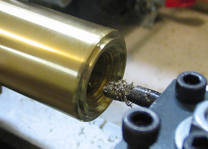
Bored the inside with a small step to catch the boiler shell.
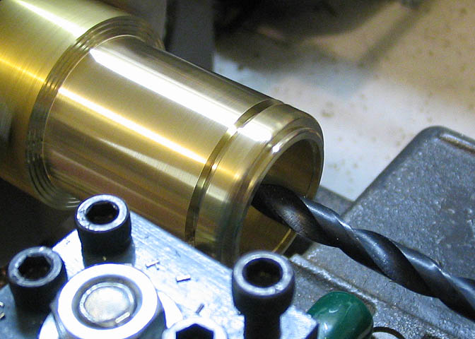
Then part each piece off. The drill bit is there to catch the piece as it falls off the parent stock.
Then cut up six lengths of 1" brass tube for the boiler shells. Here they are being parted to length.
I cut them a bit too long to start with. Better too long than too short..
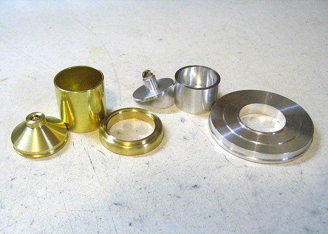
Here are the pieces for one boiler/base unit, so far.
And the group shot.
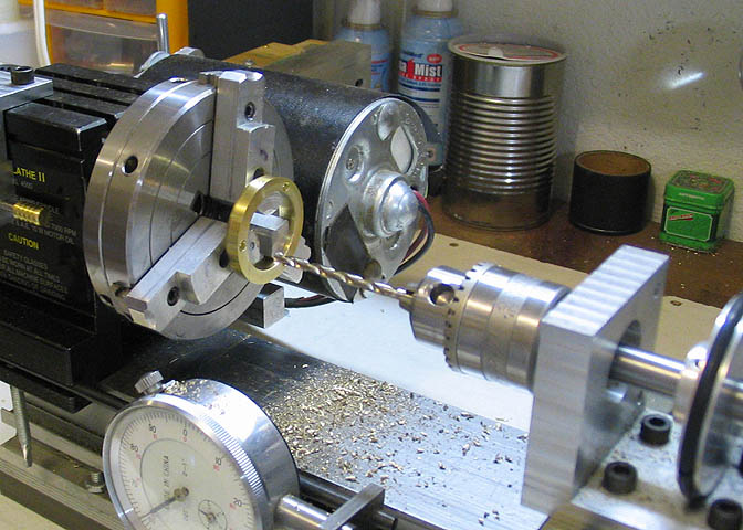
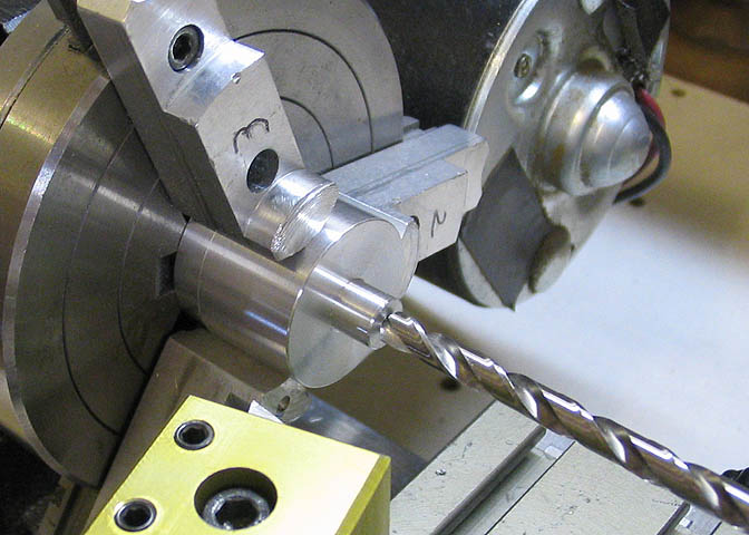
Each boiler bottom piece is drilled so I can attach the legs. The thing doing the drilling is an attachment
I made for the cross slide on my small lathe. It has a drill spindle and its own small motor. The holes in
the bottom of the boiler are spaced at 120 degrees apart. I have a small index plate on the other end of the
lathe headstock that makes sure I get the holes in the right place.
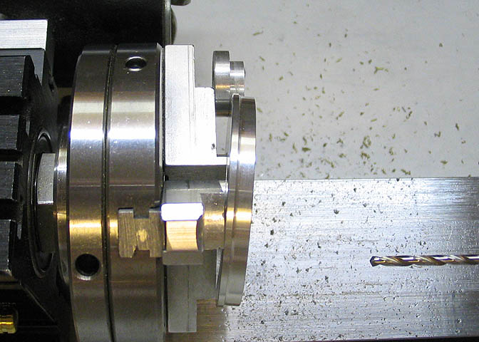
The large base pieces are also drilled with holes spaced at 120 degrees, to match the piece done in the last
step. Since the legs that go between the base and the boiler bottom are tilted at an angle, these holes must
be drilled at an angle too. I made an accurate drawing of this assembly before starting this step. Then I
measured the angle that would be needed. Using a little geometry, this allowed me to make a spacer of the
proper thickness to put under one side of the base piece while I drilled, giving me the proper angle.
You can see the spacer at the top of the picture. It has two diameters. The larger diameter is the proper
thickness to give the needed angle. The smaller diameter is there to prevent the spacer from going too far
under the base piece, which would change the angle.
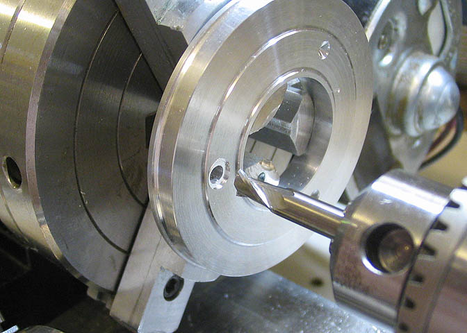
After each hole is drilled, an end mill is used to make a small spotface, again at the same angle as for the
previously drilled holes. This will let the legs sit flat when they are screwed down.
Time to go on to Part 2.
Go to:
Part 1
Part 2
Part 3
Part 4
To go back to the main projects page, click the link below.
More Taig Lathe & Mill Projects
Copyright 1998-2012 Dean Williams