Building a Small Screwless Vise
Part Three
(Part One is Here)
(Part Two is here)
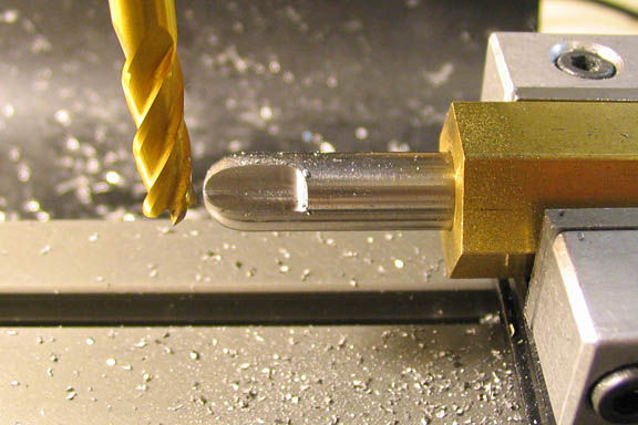
A cutter needs to be made to cut the button recess in the top of the moveable jaw.
W-1 drill rod, 3/8" dia is used. A radius is cut on the end to form half a sphere. A
radius cutter would be nice, but that's a project pretty far down on my list, so I just cut
a large chamfer on the end of the drill rod, and then used a gage and a file to finish it.
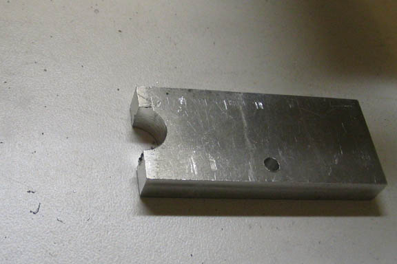
The gage can be easily made by milling out half the diameter with a 3/8" end mill. If a
gage is needed that can't be made with a standard sized end mill, the proper sized
drill bit can be used. Drill a hole in your gage plate, and mill half of it away.
While I'm at the lathe, might as well make the pivot button, too. Another piece of 3/8"
rod is chucked up, faced off, and before cutting the radius on the end, a spot is drilled
with a center drill. The radius is then turned, and a clearance hole for a 10-32 screw is
drilled, 1/2" deep.
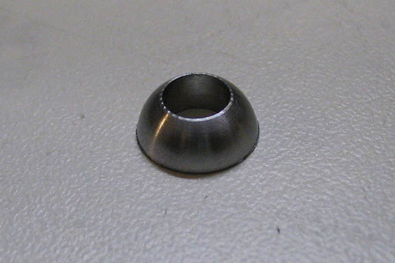
Then the button is parted off just behind the radius.
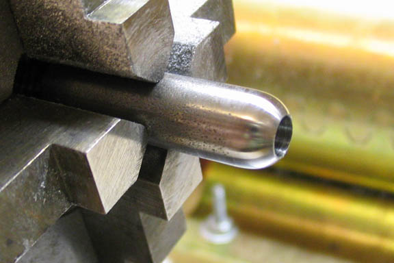
Back to the cutter now, a piece of hex rod is used for a positioning fixture. The hex
rod is bored for a running fit with the drill rod and a set screw hole is drilled and tapped.
The cutter is milled, rotating the hex rod two flats after milling each cutting edge.
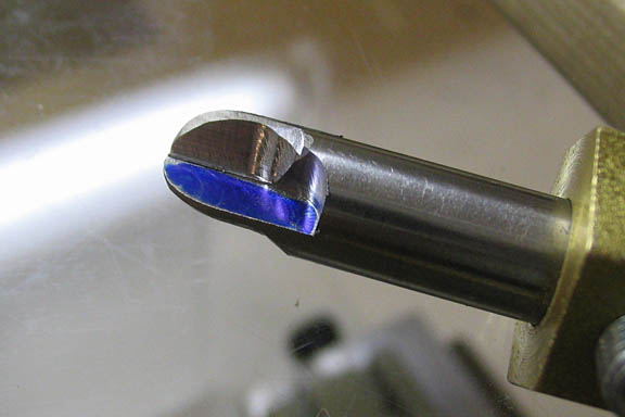
After milling, a Dremel tool is used to grind a small relief behind each cutting
edge. It would be better to make a jig for grinding the relief, but since this is
probably the only time I will use this cutter, the hand grinder will work fine. You
just have to be careful to keep the grinding disc behind the cutting edge of the cutter.
The blued area is the face of the cutting edge. I blued it so I wouldn't grind the
relief on the wrong side of the cutting edge. Rotation of the mill spindle needs
to be taken into account when preparing cutters.
After honing the face of the cutting edges, the cutter is hardened and tempered,
then honed again as necessary.
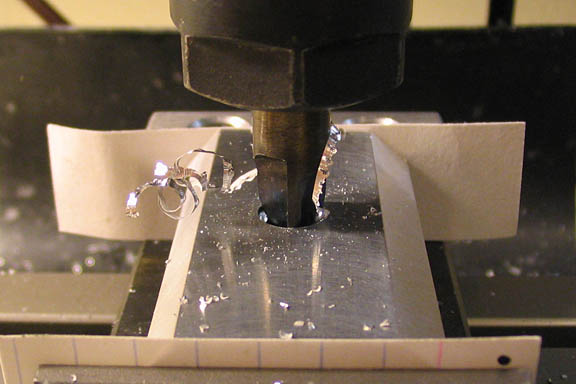
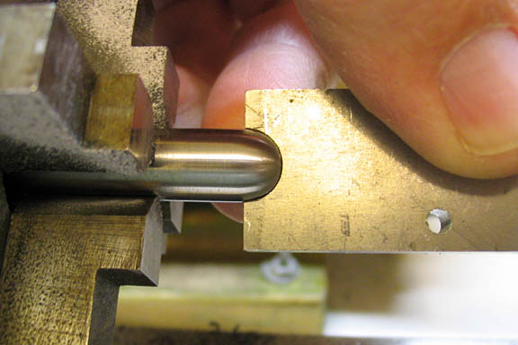
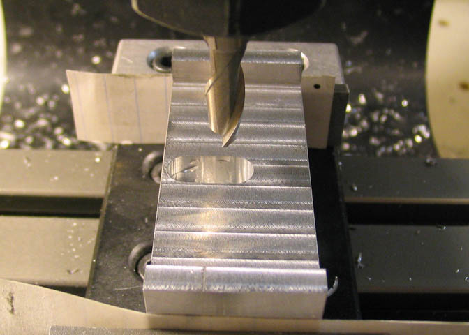
The movable jaw is put back into the vise and located via the counter bored hole
that was milled in an earlier step. The existing #10 clearance hole is drilled out to
1/4" and then the button pivot cutter is mounted in the mill spindle. The cutter has
a very flat face on the cutting edges, so it is run at the lowest spindle speed and advanced
a little at a time, checking often until the button fits nicely in the pivot hole.
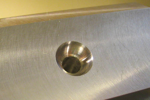
The finished button pivot hole.
Now a pocket is milled in the bottom of the moveable jaw to allow the screw to
pivot when tightening down the jaw. The pocket is milled right up to the edge of
the clamping side of the jaw, and toward the back of the jaw just until the end mill
comes to the back side of the pivot hole, being careful not to cut through the jaw.
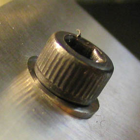
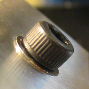
These shots illustrate how the pivot button moves as the jaw tightened.
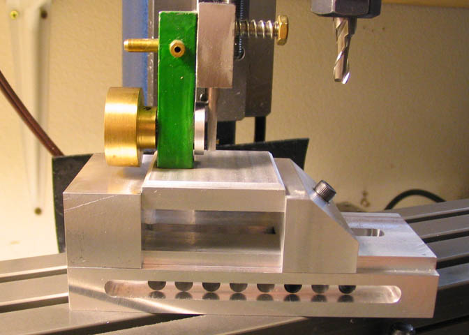
So there it is, actually clamping something! It's 2.25" wide and will take a 3" work piece
if used as it is. It will get brass jaw liners when time permits.
Thanks for having a look.
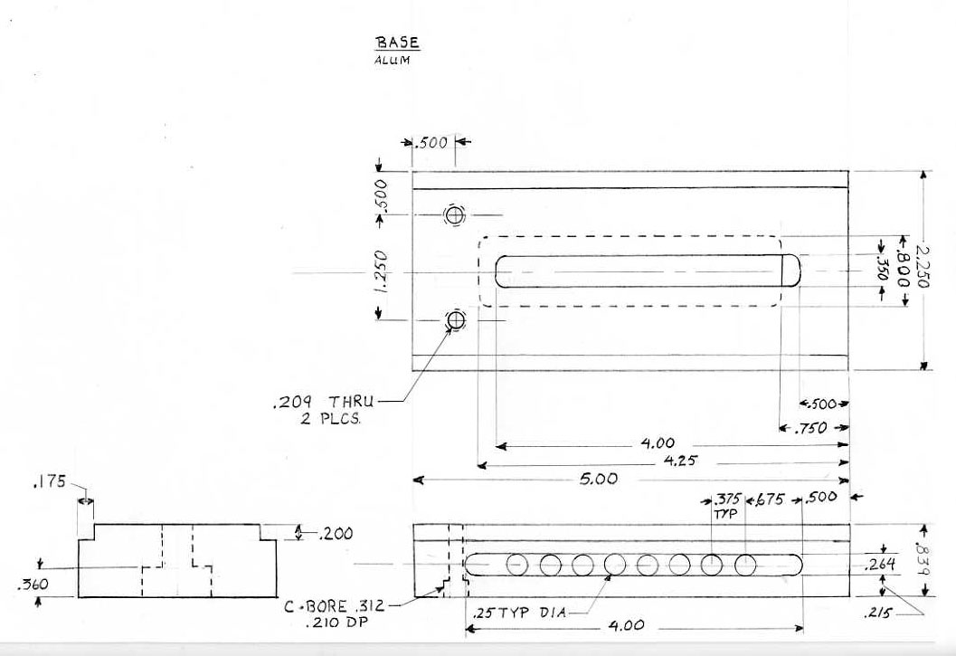
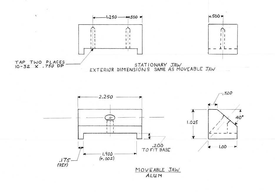
A few sketches follow. All units are in inches. Click on one to go to a larger size.
These don't represent proper drafting conventions or practices. They are just sketches
with some dimensions. For clarity, not all aspects of each piece is included in each view,
but there should be enough here for most folks.
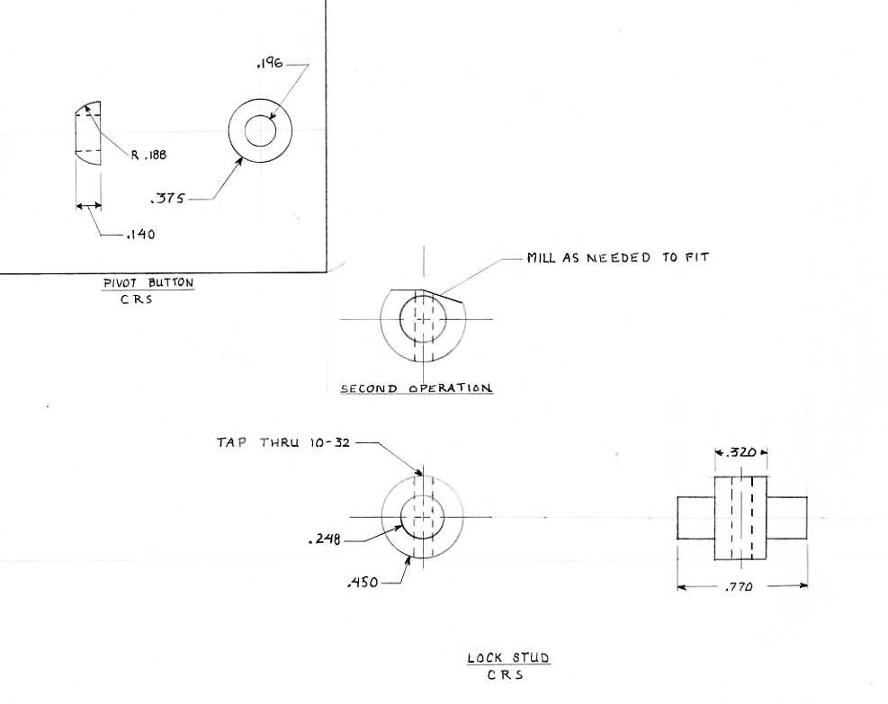
Someone might notice that on the third drawing, the radius called out for on the pivot button
is .188", when the diameter of the button is noted as .375". Obviously, the radius should
read .1875". If you want to use the sketches as a guide, look them over well. Everyone
makes mistakes, and you may find some here.
A nice fellow named Steve Campbell sent me a CAD drawing he made of the vise.
It's a PDF file, so should open if you have Adobe Reader. Thanks much, Steve!
CAD Vise drawing by Steve Campbell.
Go back to Part Two
Go back to Part One
More Taig Lathe & Mill Projects
deansphotographica.com
(home page)
Copyright 2009 Dean Williams