Building a Small Screwless Vise
Part Two
(Part One is Here)
(Part Three is here)
There is a sketch on the third page
Now, time to work on the jaws.
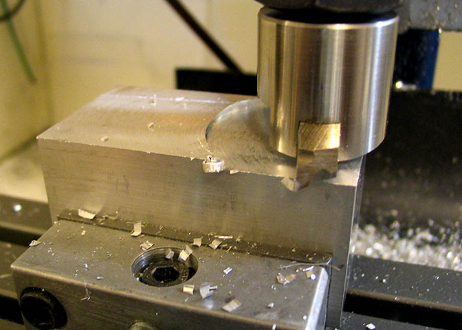
A piece of 1 1/4" square aluminum stock is used for each jaw. Here, one jaw is being fly cut in
steps of .050" per cut until it's down to the required size. The sketch has the dimensions for the jaws.
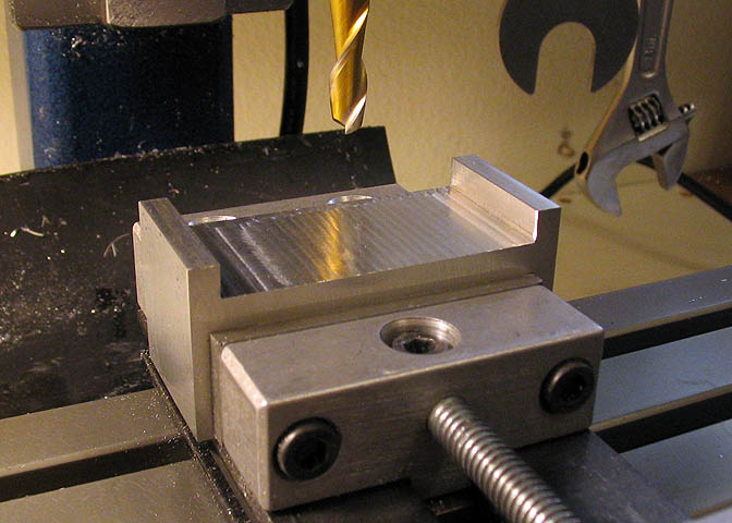
Once the jaws are brought to size, the middle section is milled out. The two "ears" will fit over
the grooves milled in the top of the base. The stationary jaw is milled out so it is a snug fit
in the base grooves, but the moveable jaw is given an extra .001"-.002" so it will slide easily
along the top of the base of the vise.
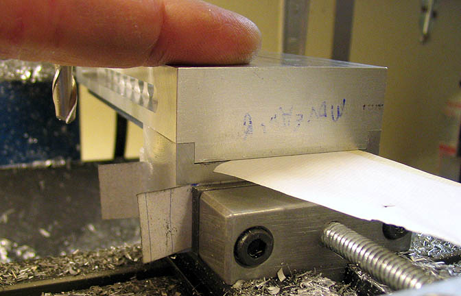
Test fitting one of the jaws to the base. Using a piece of cigarette paper, lay the paper in the
recess in the jaw and push down on the base firmly. The paper should be held tightly. I keep
a pack of rolling papers in the shop just for things like this. Also good for finding the "touch point"
between a tool and work piece.
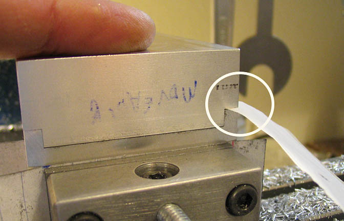
The same test is done where the ear on the jaw meets the groove in the base. At this point on
both sides, when pushing down on the base the paper must be able to be pulled easily from the
two pieces. See circle in above photo. If the paper does not come out easily when doing this
test, skim a little off the surface of the jaw at this point where the two parts meet.
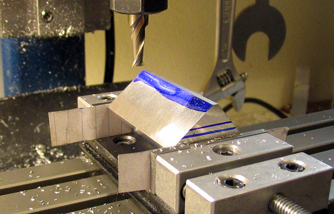
Now the moving jaw is placed in the vise to cut the back angle on the jaw. The angle is 40 deg
measured from the top surface of the jaw. The piece is milled down until there is .350" of the top
surface of the jaw remaining. The two blue lines on the end of the piece were just for a reference
so I didn't forget to do something... or didn't do something too much.
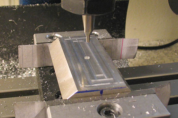
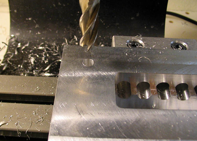
Once the angle is roughed out with an end mill, find the center of the rectangle that has been
formed and spot drill it for the hole that will carry the tightening screw. Since it is not critical
to have this hole located to the last thousandth, I put a sharp stylus in the mill spindle and
used a loupe to visually locate the long edge. The short edge can be found directly
with an edge finder or by finding the touch point using an end mill.
After spot drilling, a hole to pass a #10 screw is drilled through to the other side.
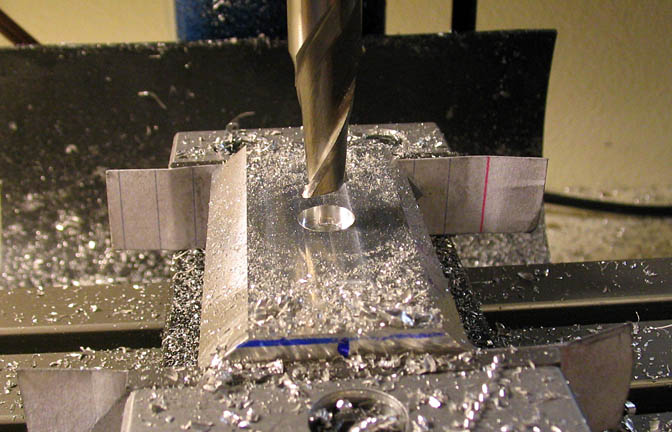
Now a shallow counter bore is made with a 5/16" end mill. It only needs to be about .050" deep,
as it will just serve as a pilot for the button recess that will be bored later.
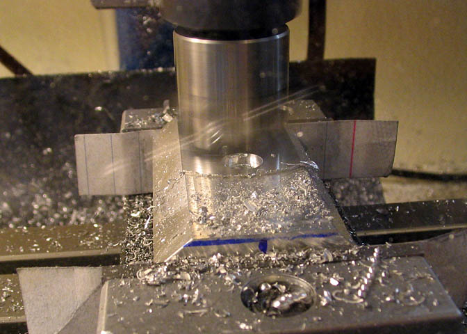
To finish this surface, it's fly cut for the remainder of the cutting job. It just needs to be taken down
until the width of the top surface of the jaw is .32".
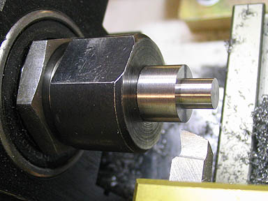
Now to the lathe for a minute, (left photo) to make the locking stud, or whatever this little widget is called.
The larger diameter is .450" and is .320 long. On each end the smaller stud is .248" dia with a length of .225".
Just checking for fit in the photo on the right.
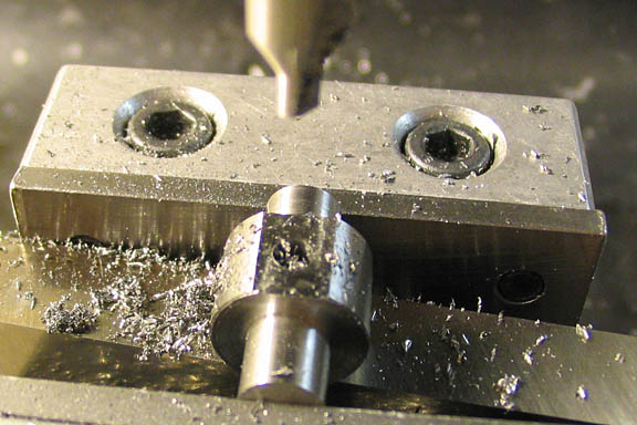
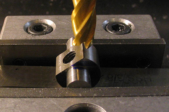
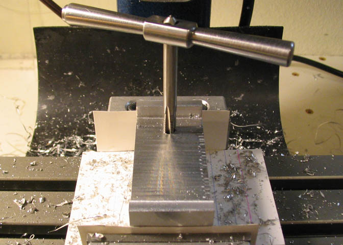
When the piece is finished in the lathe it's taken back to the mill and a flat is milled for a spot drill.
Then it's drilled through and tapped for 10-32. The flat was milled somewhat larger than shown here.
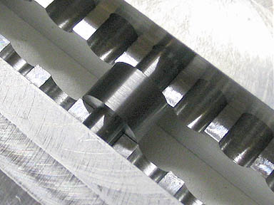
The piece is test fitted in the base again, this time with the moveable jaw and screw, to find the bottom
of the locking stud. It is set on one of the high points between the cut-outs and marked for the depth of
the flat that needs to be milled away, and another flat is milled. This flat is to prevent the stud from
dragging on whatever surface is below the vise when the stud is repositioned to the various cut-outs in
the bottom of the vise base.
Here the base is drilled for mounting the stationary jaw. The holes are .209" dia. and are positioned
.500" in from each side, and from the end of the base. After through drilling these holes, a 5/16" end
mill is used to counter bore them enough to clear the head on a 10-32 SHCS.
These holes must be accurately located.
The stationary jaw is now drilled and tapped for 10-32 screws. The holes are drilled for the same
position as the base in the previous paragraph, and again, must be located accurately. They are
drilled 3/4" deep and tapped to the bottom. The tap holes are not drilled through to the top of the jaw.
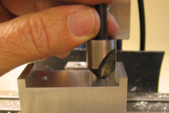
Tapping, boring, and milling holes brings up a bur at the periphery of the hole. A chamfer or
counter sink bit can be used to remove the burs from the tapped holes in the bottom of the
stationary jaw so they won't interfere with the fit of the jaw. Same goes for the counter bored
holes in the bottom of the vise base. Just turning the chamfer by hand is enough.
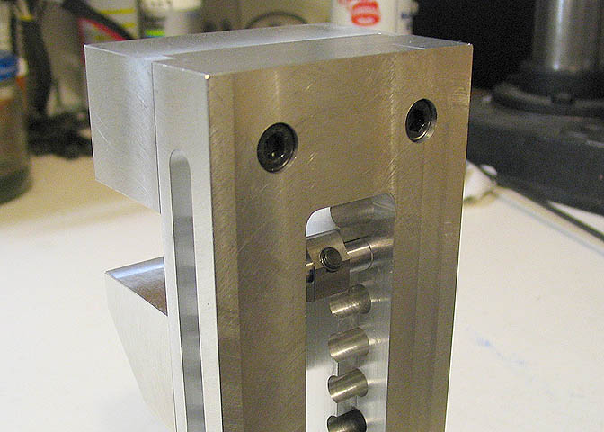
The back side of the stationary jaw mounting.
Go to Part Three
Go back to Part One
More Taig Lathe & Mill Projects
deansphotographica.com
(home page)
Copyright 2009 Dean Williams