Building a Small Screwless Vise
Part One
For the Taig, and other small mills.
My Taig mill came with one of their small milling vises. It is okay for some small work, but
it's hard to keep it accurate, due to the way it's built, with the long screw and "floating"
moveable jaw. It's more like a small drill press vise.
A precision screw vise would be nice for the mill, but most of them are too big for the Taig.
The "screwless" type of vise is pretty accurate, (although where it got it's name, I can't imagine).
The moveable jaw is pulled down as the vise is tightened, so the work piece isn't pushed up
against the stationary jaw, making accurate set-ups easier.
These are a common vise, for sale at any tooling store. One can be had for the price of two
or three good quality carbide end mills. I'd rather spend the money on the mills.
There is a simple sketch with dimensions on the third page.
This is the piece of aluminum stock I started out with. I know a few guys at a local welding/fab shop
and I stop by to rummage through the scrap pile now and then. They sell it to me by the pound,
and a two foot long piece of this stock cost me $2. It had set out in the wet Idaho weather for
so long that it appears to have grown moss. It's actually a bad case of oxidation, which the fly
cutter will shortly remove. The piece is kind of an odd size at 7/8" thick by 2 3/8" wide. I cut
it with a power miter saw using a common carbide tipped blade normally used for cutting lumber.
This type of blade will cut aluminum much the same as it will cut wood. Just a little slower.
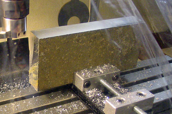
The top edge has been fly cut.
Anyone who has done much fly cutting knows that the process flings chips far and wide. You'll
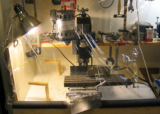
have chips where you don't even have places! When fly cutting is necessary, I cover the mill
with a piece of window film, as shown in the photo above. It's attached to the edge of a shelf
above the mill using double sided tape, and draped over the mill. I have a kicker board mounted
to the edge of the bench, and the film is held to the board with foam pipe insulation. The foam
tube just wraps over the edge of the board and pinches the window film in place. Takes about
five seconds to remove the foam and lift the window film over the top of the mill to get it out of the
way for set-ups, or for doing other operations where the film is not needed.
Mainly, it saves a lot of clean up. About 95% of the chips are contained by the window film.
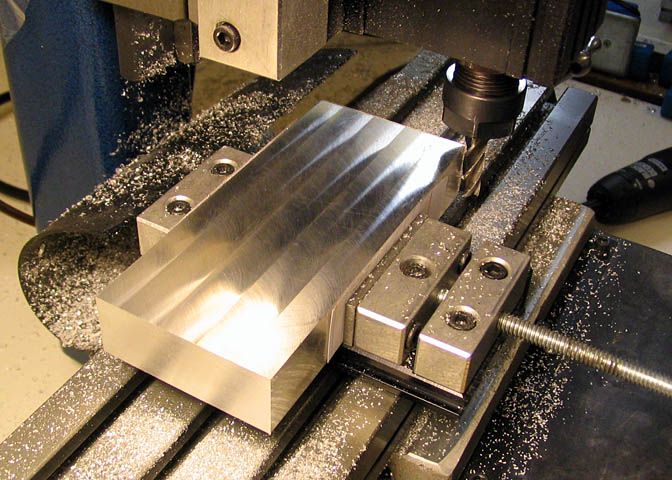
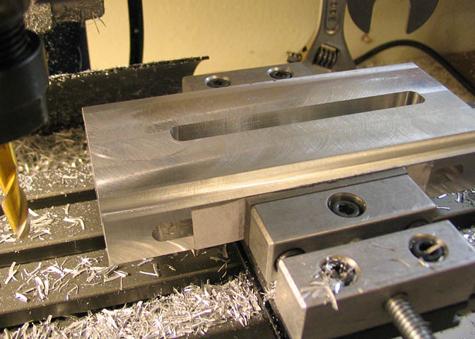
Here an end mill is run across the far end of the work piece to clean it up and true it.
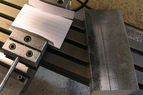
This is the last side to be machined. Index card was used in the vise to protect finished surfaces.
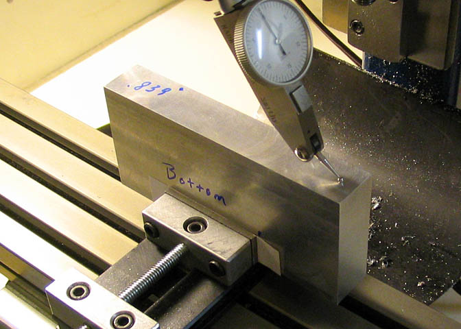
Now one of the long edges is indicated in before drilling the holes. It needs to be indicated
to be sure it is perpendicular to the spindle.
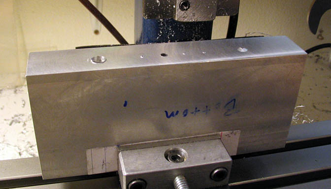
Note that the bottom has been marked. Saves mistakes later on. I also marked the edge
thickness as can be seen in the photo, just for a reference. The piece wasn't machined
especially for that thickness. It's just what the piece cleaned up to. It can be any useable
thickness, as long as it will accommodate a clamping groove, the diameter of the holes, and
the edge groove that will mate with the bottom of the jaws.
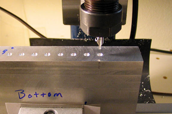
The hole locations are center drilled. The first hole is located using an edge finder, and the
remainder of the holes are dialed in using the X axis.
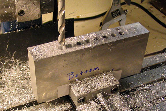
After center drilling, take up the back lash and dial back to the starting point. Then the holes
are step drilled, first 15/64", then cleaned up with a 1/4" bit. Drilling the holes took longer
than any other operation. Each hole had to be cleaned out five or six times to keep the bit
from becoming plugged with cuttings.
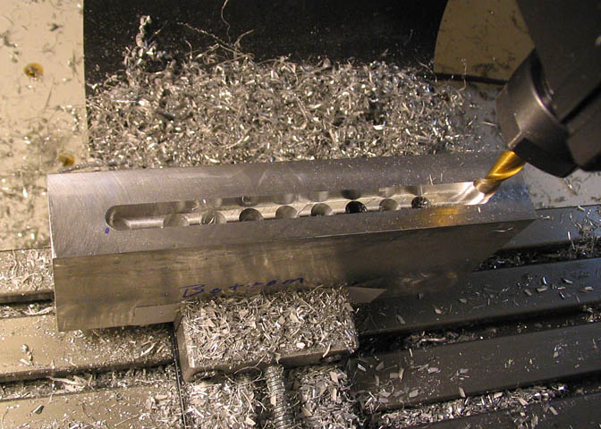
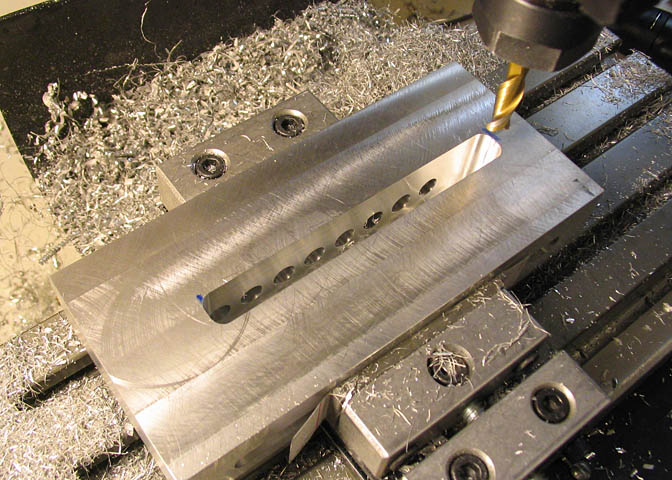
After the holes are drilled, and without disturbing the set-up, the clamping pocket is milled.
A 1/4" end mill is used, with .250" depth of cut in two passes. Another .005" is taken on either
side of center line so a 1/4" thick clamp will fit easily. A final .001" is taken on each side of the
cut with the end mill being fed in an "down" rotation for a nice finish, (only on the last pass. All
other operations are "Up" milled, i.e. using normal feed direction).
(Note: "Down" milling should only be done in very light cuts on small machines. If a heavier cut is
attempted, many bad things can happen. Backlash in the screws can let the miller suck the work
into it. This can lead to a number of situations. The end mill may simply jam in the work, stalling
the machine. The end mill can also suck the work into it so hard as to break the miller itself, and in
some cases the work can be pulled completely out of the clamping device and flung across the room.)
Now, with one clamping pocket milled out, the piece is flipped end for end and the pocket on the
other edge is milled in the same manner. If the work piece is repositioned in the vise with the bottom
facing you as in the last step, the only thing you will have to locate is the distance of the pocket from
the end of the work piece. The edge to edge coordinate will not need to be relocated, since the bottom
of the piece is still in the same plane as in the first pocket milling operation.
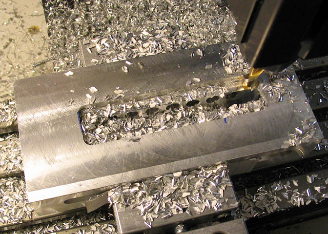
It can be seen that I drilled through on a couple of the holes, (on purpose), but I had intended to leave
the holes in the middle just shy of breaking through to spare the little Taig vise any scars. Well, it can
also be seen that one hole in the middle did come through just a touch, which left a little "doink" in the
vise. It happens.
(Here's a little ramble. Skip it if you like...)
I had a little Sherline mill for about seven or eight years and used it a lot. I never put a hole in the vise
on that machine. Maybe I was just lucky, or maybe I was better at counting the rotations of the Z lead
screw. I have a a drill press vice that I've owned for about 20 years, and it has one little hole in it, and
I remember doing it. I was careful every time I used it over two decades except for that one time.
It happens.
I worked in a fair sized fab shop at one time. I worked as a welder, and since I had a (larger) lathe and
mill in my home shop at the time, the boss would send machine work home with me on the weekends
to keep me busy. At that job, the whole shop shut down for two weeks every Christmas. I got the same job sent
home with me for three Christmas vacations in a row. The shop had a big ol' Wilton gear head drill press.
That thing would really hog a hole. Mounted on it was a large American made milling vise that would
take about a 7" work piece. That vise weighed about 115 pounds. Everyone in the shop used that drill
press and vise, and on the first Christmas vacation that the boss sent the vise home with me, it must
have been about 10 pounds light. It had that many holes drilled in it. It was cast iron, and it took quite
a while to weld up all those holes and mill it all flat again. I took it back to the shop on the first Monday
after vacation, put it on the drill press table, and went back to my welding section. About mid-week,
the boss called me over to the drill press, pointing an accusing finger at two new holes in the vise.
Wasn't me! (I'd been welding, day in, day out.) But it happens.
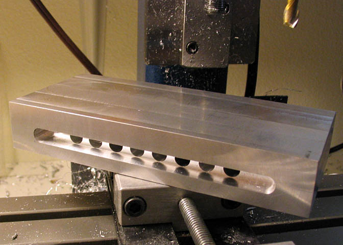
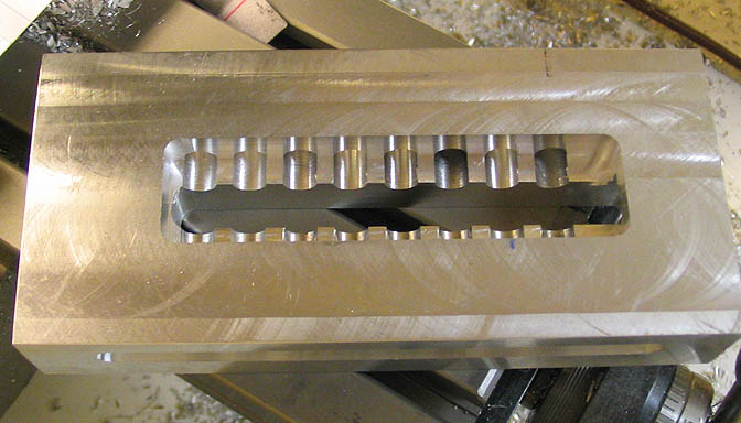
So, here we have the piece with both clamping pockets milled, ready for the next step.
Now the pocket for the clamping yoke is milled in the top side of the vise base. The slot is .350"
wide and done with a 1/4" end mill. This can be milled as deep as you like. I just made sure that
I milled through to the bottom of the cross holes. The rest of the work is done from the bottom of
the base plate.
Beginning the pocket in the bottom of the base. The cross pin for the moveable jaw will be 1/4"
diameter by 3/4" long, so the pocket needs to be somewhat over 3/4" wide. I made this one .80".
The main thing to be sure of is to mill enough away from the cross holes so that the cross pin will
slip easily into them. It can be cut to a specific depth, which will depend on how thick you decide
to make your base, or you can cheat a little by milling down until you just see the top, (bottom, really)
of the cross holes starting to peek through, and then another .125", which will effectively cut the
holes in half.
The bottom pocket finished.
Next the grooves for the jaw are milled into the base. One long edge of the base is indicated
in before milling this step to assure that the two grooves run parallel to one another. It's
important to be sure the top of the base plate is flat before beginning this step. (In other
words, indicate the top, too...)
Go to Part Two
(Part Three is Here)
More Taig Lathe & Mill Projects
deansphotographica.com
(home page)
Copyright 2009 Dean Williams