An Indexer Project
(I wrote this about seven or eight years ago. At the time, the digital camera
I was using for pictures wasn't much for resolution or file size, so the pics
here aren't so hot. There may be something of interest here, nonetheless.)
One of these days, while I'm building some of the things on my projects list, I'm going to need some items
that will need precisely spaced holes and/or teeth ( for gears and bolt hole circles, etc. ). Laying out
more than six holes in a flywheel gets a bit iffy for me, and laying out the teeth of a 30 tooth gear is out of the question.
The old time watch makers may have been able to do it, but it's completely beyond me.
So what I need is an indexer.
Just as a Boeing 747 is another version of the Wright Brother's Flyer, this tool is my version of what must be
many dozens of similar tools. I rummaged through my scrap bins for a while, made a pile of chips, and this is what I came up with.
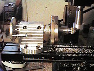
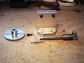
On the left is the finished piece with a Sherline chuck mounted for holding an arbor, which in turn holds
the gear blank. The right shows the main pieces and sub assemblies.
The first thing you will need, of course, is the main body. Since I'm using Sherline machines for this project,
and this is kind of a large piece for these machines, I chose aluminum for the material. It's easy to machine,
and plenty strong for this project, considering the size of gears a person would make on this size of machine.
You can use steel, of course, and these machines will do a good job of it.
It will take more time to complete the project, though.
I had to use a larger vise than the standard Sherline item in order for the jaws to open up wide enough.
I made the body out of round stock because I had a bunch of it, but you could use square stock with excellent
results if you have some. The diameter of my piece of stock was 2 5/8". I got this stuff at a screw machine shop.
They were making faucet fixtures out of this particular diameter of stock. Once it gets down to about six
or seven inches in length, it will no longer feed through the screw machine. The scrap (drops) are stored in barrels
waiting to be recycled. I asked to buy some, and the owner sold me a dozen for $5.00.
He had lunch money and I had more precious junk.
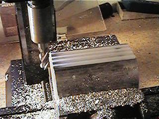
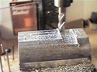
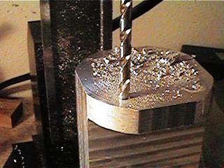
The first step is to make a flat spot (left pic). Make it about 15/16" wide. (How's that for precise?
Actually this dimension isn't critical. It could be slightly more or less, but make 'em both the same.) When
you have this done, turn it over and make another like it on the other side. Now you should have two flat spots parallel
to each other. You will use these two flats to orient the piece in the vise. The main milling is going to be perpendicular
to these two surfaces. So, roll the piece 90 deg. and lock it in the vise with the two flats against the jaws. Make
sure everything's square. In the pic on the right you can see one of our flats showing above the movable jaw of the vise.
The action's up on top now, and we're just beginning to make what is going to be a big gob of chips.
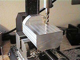
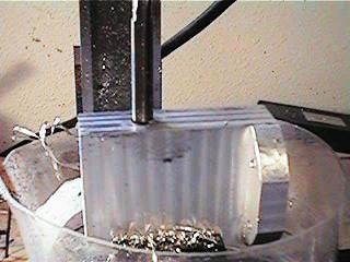
The pic above shows one side of the body finished, and I'm about to run the mill against the vertical surface
of the base for the finishing cut. When this is done, turn the piece over and mill the large flat on the other side. It is
milled down until it meets the flats on the sides of the body.
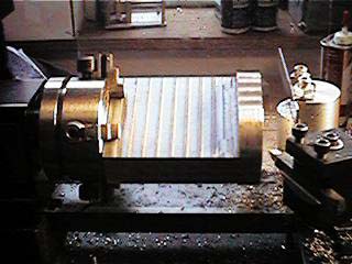
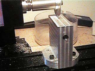
The shot above shows the piece mounted in the four jaw. Indicate the small flat to run parallel with the ways
of the lathe. Now take a facing cut on the bottom of the body. Take light cuts until you have a nice flat surface.
This will make the bottom mounting surface perpendicular to the sides that the mounting arbor will extend
through. This is one of the critical parts of this piece. If you don't get it right the mounting arbor will not run
true in the body. Now flip the piece end for end and face off the top of the body.
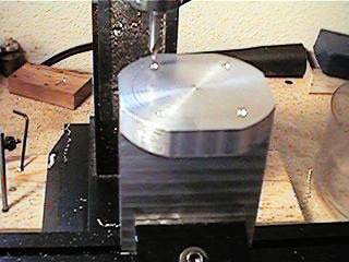
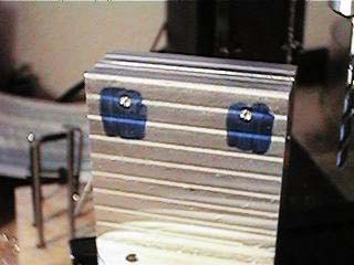
Now it's back to the mill (or drill press) to drill the mounting holes in the base (above). If you are going to
mount the indexer on a Sherline machine you will need to countersink the bottom of the base to allow for the
Sherline t-nuts. Lay out the holes to suit your particular machine.
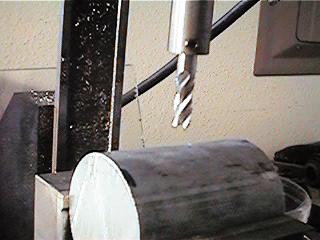
The next thing we need to do is locate, drill and ream the hole for the arbor (above, left). After this
is done mount the body to your mill table as if you were going to use it, and cut the .030 slot in the top.
Make sure the body is square on the mill table, or you will end up with a crooked slot. Once the slot is
cut, run the reamer through the hole again to clean up the edge that the slotting saw will leave on the inside
of the hole. You should be able to do this by hand.
Now lay out the holes for the locking screws in the top of the body. Drill clearance holes on
one side of the slot (the side that will be facing you when the indexer is in use) and drill and tap
for 10-32 on the opposite side of the slot. There is one more hole to drill and tap on the left hand side
of the body (see print in the "Prints" link, below). The body for the indexer is now finished.
This piece takes the most time to complete due to the amount of milling.
There are a couple more pages for the other parts needed:
Indexing Pin Assembly
Dividing Disc assembly
Indexer Arbor
Prints For Each of the Pieces
So, I got a Taig..
(The start of my little machining section)
deansphotographica.com
(home page)
copyright Dean Williams
Feb 2000