Making a Boring Head for the Taig Mill
Part Three
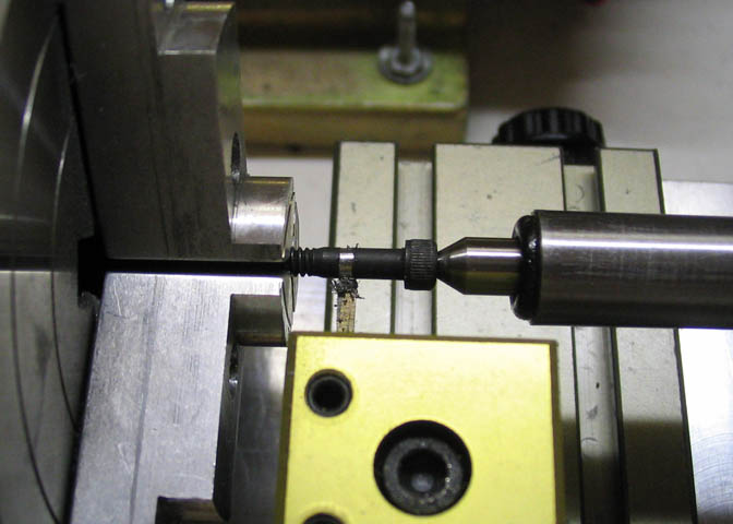
To cut the smaller diameter on the lead screw that will fit in the retainer block, I put it in the
three jaw chuck, and used a live center in the socket end of the screw. This will work okay as
long as a live center is used. A dead center probably won't do, as it will rub on the flats
inside the hex head of the screw.
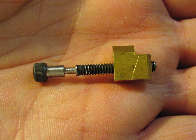
Here's a shot of the finished lead screw and nut.
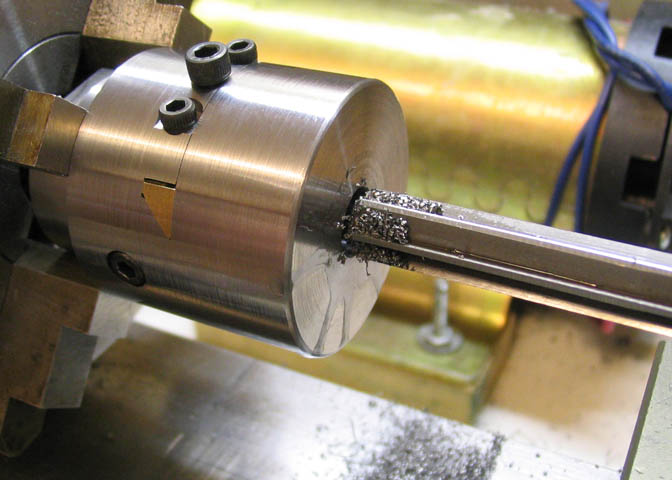
The assembled boring head is put back in the four jaw chuck and dialed in. The hole that
was spotted earlier is drilled and bored to just under .375". The boring bar is also used to
face off the bottom of the bore to get rid of the cone left by the drill bit. Then the .375"
reamer is run to the bottom to bring it to size.
I had waited to do this step of boring the off set hole until the lead screw and it's associated
parts were done because I had figured on using the screw to dial in the off set. As it turns
out, I hadn't thought this all the way through. The lead screw will not draw the slide back
past the point of the center line of the inside hole, so it couldn't be used anyway. For this
hole, the lead screw and it's parts were removed, and the slide is offset using a caliper to get
the hole spacing called for in the print.
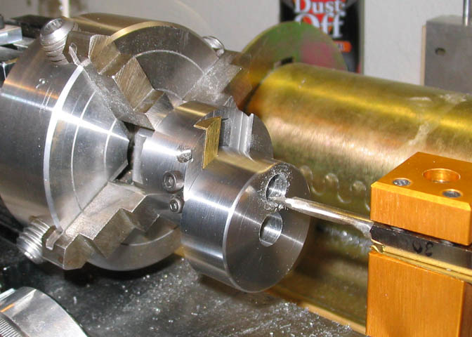
I only put two holes in the slide, as seen in the above picture. I'm not sure that a third hole is
needed since all the diameters the boring head can bore should be able to be achieved with
just the two holes. The extra weight left where the third hole would have been should also
help with the out of balance vibration that will occur when using the head at it's extreme
set over.
Something that should be noted when turning this, or anything that has a substantial weight
that is off the center line of the lathe spindle, is that it will vibrate. The faster you turn it,
the more the vibrations will increase. No doubt, some will feel I'm stating the obvious, but
the potential for damage to the lathe and worse, a very real chance for personal injury makes
this worth mentioning.
If the lathe has a fixed speed motor, then even starting on the slowest speed on some small
lathes will be too fast. The Taig lathe that is being use here has a minimum speed of about
500 RPM when using the standard pulleys and a single speed motor. That will provide a
good deal of vibration. If the lathe were started with the pulley set at, say, 2000 RPM, it
would probably shake violently. I happen to use a variable speed motor on my lathe, and
can run it as slow as needed. If your lathe will not run slow enough to do this step safely,
consider doing it on the milling machine. The piece will need to be set up very carefully to
assure getting the holes in the proper place.
If a milling machine is not available, (for instance, if you were making this boring head for
use on the lathe, and it is your only machine), then consider rigging up some sort of counter
weight on the main body of the boring head, offset in the opposite direction from the extended
slide. A metal hose clamp and a few strips of lead stick on wheel weights will probably be a
good starting point.
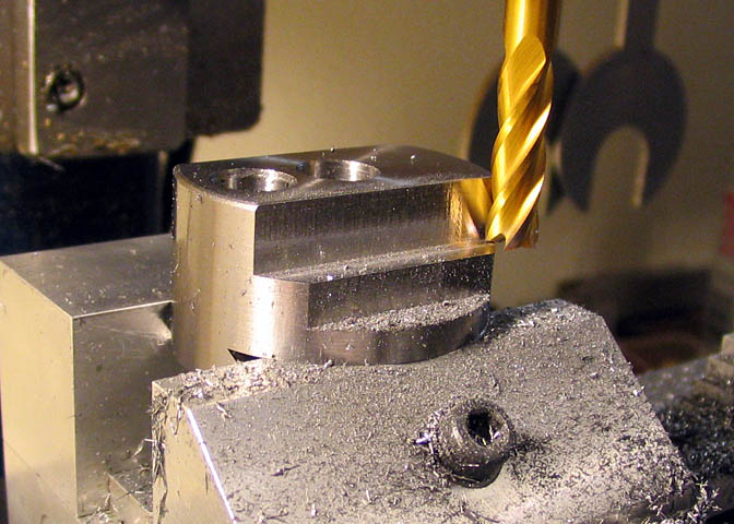
Now the boring head is getting down to the last few finish steps. This one takes a little
while, since there's quite a bit of material to be removed, and some of it has to be done
with a ball end mill, which calls for light cuts and feeds. To start the removal of material
that will become the flat sides and radiused corners of the slide, a regular end mill is used
to remove all metal possible before beginning work with the ball mill. At the point shown
in the picture above, all has been cut away except a "step" that is equal in height and
width to the radius of the ball end mill.
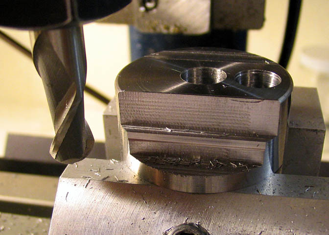
Once the majority of the waste has been removed, the ball mill can be used to finish it up.
If you have a four flute ball end mill, that's great. It will cut much better than a two flute
on steel. The only ball mill I had close to the size needed is a two flute, so it makes the
going a little slower. About the most that can be cut with this type of end mill is .005" per
pass. If it is pushed too hard, it will dull quickly. Also, I rarely use any kind of cutting
fluid, whether on the lathe or milling machine. In the case of a ball mill though, it really
is needed to get any kind of cutter life out of the tool.
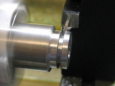
There are still a couple of steps to finish up the body, and one of them is to cut the counter
bore that will house the micro dial on the lead screw. It is necessarily one of the last steps,
since the boring head must be assembled to cut the bore. I had seriously considered making
a piloted counter boring cutter just for this task, and when I mentioned that to Steve Campbell,
(who designed this boring head), he suggested using a rotary table. For some reason, that
had not even crossed my mind. I'd been thinking about making a cutter since the beginning,
and that seems to have blocked out thoughts of all other solutions.
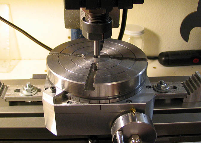
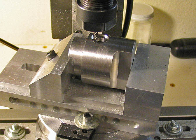
So, if you have a rotary table, here you go. Mount the RT to the milling machine, and use
a gauge rod in the mill spindle to center it with the spindle bore.
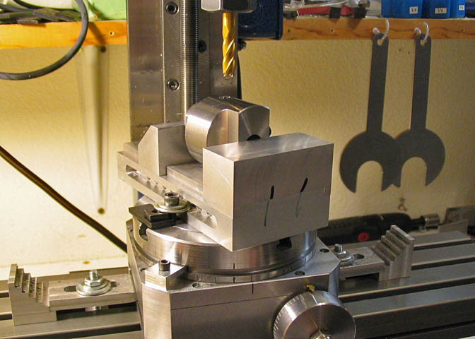
Then do the same thing with the boring head mounted in the the vise. Make sure the lead
screw hole in the head is vertical. It can be checked using a square against one of the wrench
flats, since the lead screw hole was cut to be true to them earlier on in the construction.
Both the rotary table and the screwless vise shown here were made in the shop. If you
want to read about building them, click on this link; More Taig Lathe & Mill Projects
When everything is centered nicely, the lead screw hole will be directly under the spindle
center line, and it's only a matter of cranking the dial on the X axis to increase the diameter
of the hole, producing the counter bore. I used a 1/8" end mill. They are fairly brittle,
and I figured if I goofed on the rotation of the RT and the cutter grabbed metal, it would
snap off before it could do any serious damage to the boring head. As it turned out,
taking light cuts and keeping a steady feed rate produced a nice result.
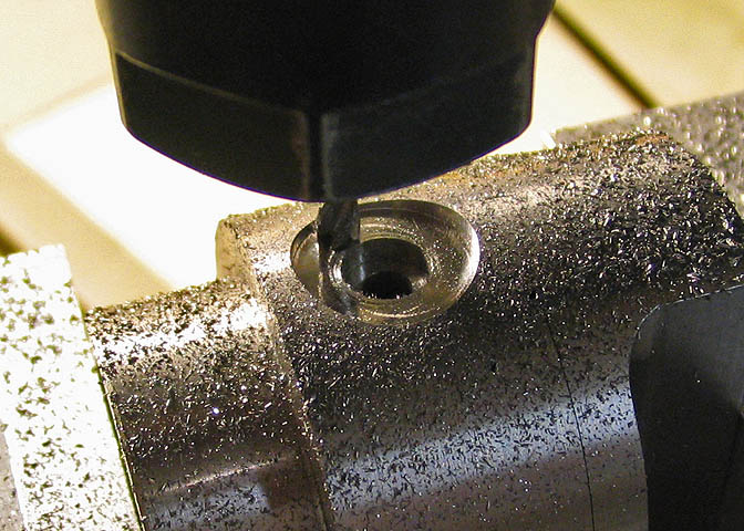
It took quite a few rotations to get this cut, but it turned out well.
If a rotary table is not available, a 1/2" end mill will work. Make sure the set up is very
rigid if you intend to plunge an end mill in to cut the counter bore. There are a lot of forces
at work when plunging that size tool into steel.
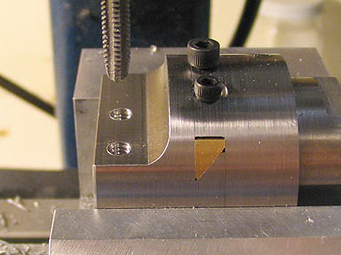
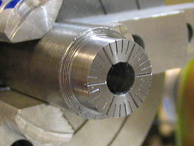
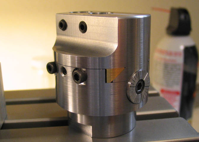
Left picture; The two holes for the tool holding set screw are drilled and tapped.
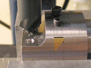
Right picture; After the tapping is done, a 90 degree countersink tool is used to clean the rough edge
left by the tap. The motor on the mill is not used. Just turn it by hand for a couple rotations.
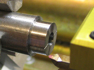
To make the micro dial a short piece of CRS is chucked up, turned down to size, and faced off. Then a hole
is drilled and bored to .001" under size of the head on the lead screw. The graduations are then engraved using
a pointed tool ground to a narrow "V" shape. The grads here are not quite the same as in the print. I used a
lead screw with a different pitch, since I couldn't come up with one as called for in the print.
The grads are made .010" deep for the long lines, and .005 deep for the shorter ones.
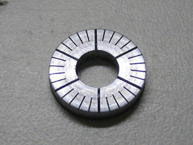
Finally, the piece is parted off and the back side cleaned of any sharp edges left by the parting tool.
The finished item is on the right. The drawings show a bevel on the face of the dial, but in correspondence
with Steve, he mentioned that he had decided to leave the one on his flat, so I followed his example on that.
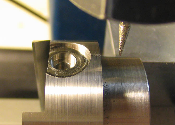
Last step(!) The index mark on the body piece is engraved with a small pointed diamond
bur. It's only a few thous deep, but I didn't measure the feed depth when I was doing it.
Just kept at it until it looked good to me. I put the index mark in a different location from
the one shown in the print. Just personal preference.
Last few notes;
The head on the lead screw is just pressed into the dial.
To attach or remove the slide from the head, the gib must be removed.
Use the center gib screw for tightening the gib. The outer screws are
just to keep the gib from falling out when you loosen the center screw.
Use as short a boring bar as possible.
With the slide adjusted to its' maximum off set, keep the speed below
approximately 500 RPM. At that speed and off set, on my machine,
a little vibration is present, but nothing that worries me. Faster than
that, and vibrations get very noticeable. The Taig is a small machine
when all is said and done, and you have to consider things like off center
rotating mass when using a tool like a boring head.
That's it!
Back to page 2
Back to page 1
More Taig Lathe & Mill Projects
deansphotographica.com
(home page)
Copyright 1998-2009 Dean Williams