Making a Boring Head for the Taig Mill
Part One
A boring head is one of those kind of tooling items that a person may use on a
regular basis, or just now and then, depending on the kind of things your build
in your shop. What ever the case, it's hard to substitute another tool for it when
it's needed. I've used a fly cutter in place of one, but adjusting the tool bit for
the size of hole needed can be tricky. The boring head has a micrometer adjusting
dial that makes this an easy task.
I came across the plans for this one when I mentioned to Steve Campbell that I
was planning to make one soon. He was nice enough to offer me the prints
for a nice one he had designed a few years ago that fits the Taig milling machine
spindle. It can be made for either the older style 3/4-16 spindle nose, or the more
recent production ER-16 units.
Steve kindly gave his permission to use his prints for this project, and you can
see them in the following link;
Taig Milling Machine Boring Head Prints.
(a .PDF file, so you need the Adobe reader if you haven't already got it)
Thank you, Steve!
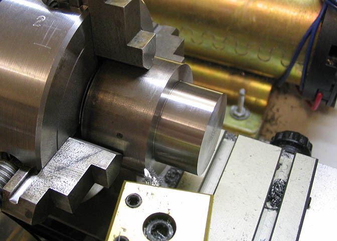
The project starts with a piece of 12L14 CRS round stock, 1 5/8" diameter and 1 1/2" long.
It's mounted in a four jaw chuck and dialed in. The piece is slightly longer than the dimension
called for in the print, to leave a little extra material for finishing the ends, and to allow a
little elbow room for my own machining habits. It just happened that the four jaw chuck
was used here, but for this the three jaw would do as well.
The end is faced off, and a diameter of 1.125" is turned for a length of .600".
Something about stock sizes;
For 12L14 round CRS, 1 5/8" is a stock size, and starting with that size makes things easier
as far as leaving a little extra OD for finishing later. If 1 1/2" stock is all that can be found, it
will do fine, but it doesn't leave any extra stock for finishing, so when it comes time to clean
up the exterior of the boring head after the other steps are done, it will end up a little under
the size called out in the prints. Not a big deal. Use what is on hand.
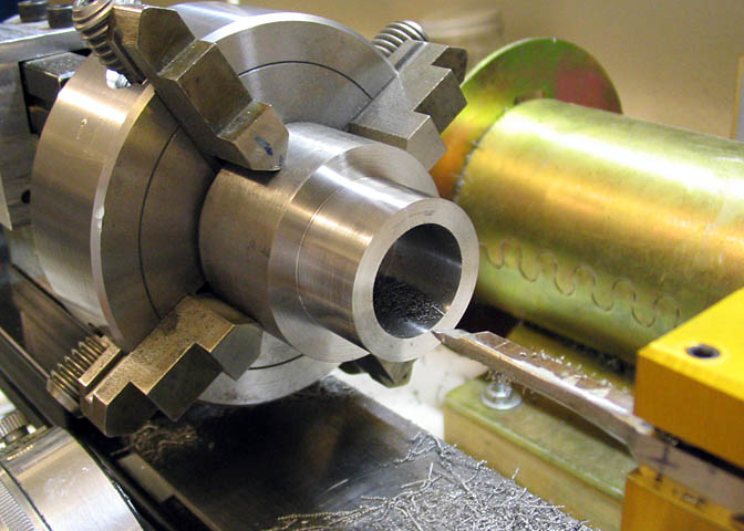
The end is then center spotted, drilled, and bored to a diameter of .815". This boring head
is being made to fit the Taig ER-16 spindle. If you're using a mill with the 3/4-16 spindle
thread, then you need to adjust the size of the bore for threading that pitch.
The depth of the hole is deeper than called for in the print, because the end of the piece
was left a little long, just for the time being. It will be brought to proper length in a later
step. This is just a personal preference. It seems easier to me to start things like this a
little long and trim back later.
When the bored hole is finished, a tool shaped similar to a boring tool is
used to face the bottom of the hole flat.
Now, some way of cutting threads is needed to make the thread that will mount the boring
head to the spindle. There are a number of ways to do this. I have an old lathe that will do
threading jobs, which is what will be used here. I think Steve said he used thread milling,
and if the shop is equipped with a CNC mill, you're all set. If there is a CNC lathe sitting
on your work bench, then you have another option. Another way to go is with a tap. If using
a tap, great care will have to be taken to tap the hole true. Certainly it would need to be done
with the lathe tail stock used to support and guide the tap. You would also need two taps, at
least. A taper tap to get the hole started, and a bottom tap to get threads near the bottom of
the hole. They don't have to go all the way to the bottom, but will need to have full threads
to within a couple of threads distance from the bottom.
If the tapping method is the only option, then it may be time to make friends with a fully
equipped machinist, or at least one who has threading capabilities on his lathe. Buying
taps for 3/4-16 isn't too costly, but if you're thinking of doing it for the m22x1.5 thread of
the ER-16 spindle, there's going to be some serious money involved. Few people will be
happy spending $80-90 for two taps that they will only use once.
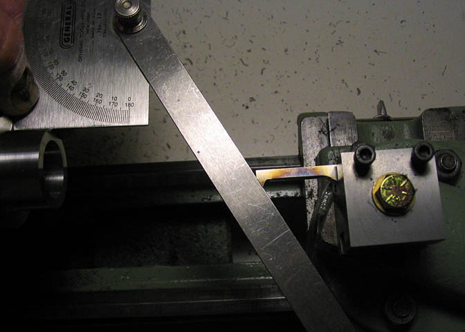
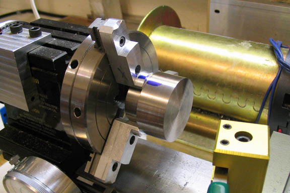
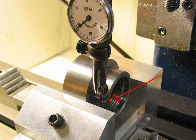
Okay, back to the picture above. I'm threading this with my old 6x12 lathe. In the picture
the angle is being set for the thread cutting tool. There was no fish tail tool with such a small
"V" gauge in my shop, so here an adjustable protractor is being used to check the angle of the
cutting tool. The protractor is set to 30 degrees and one of it's square edges is held against the
machined surface of the boring head body. Then the tool can be adjusted to the protractor leg.
With the threads cut, the first big step is done.
Might be worth mentioning here that though the turning on this piece was done on the Taig lathe,
the threading obviously was not. I made a spindle nose adapter for this old Craftsman lathe
that is doing the threading chores. The adapter lets the Craftsman use the Taig chucks, so when
the turning was done on the piece, the entire chuck and work piece were transferred to the
threading lathe without ever disturbing the jaws of the chuck, or the piece it's holding.
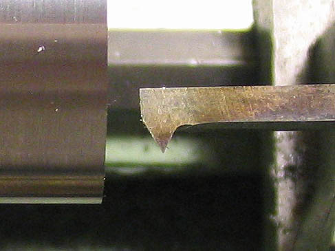
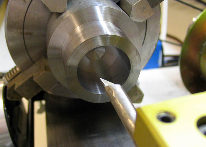
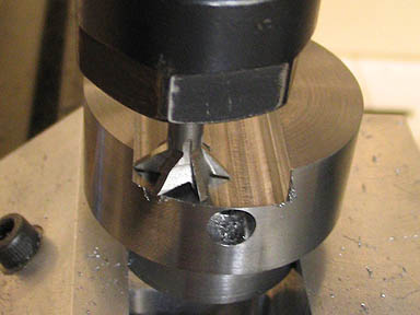
A close up of the internal thread cutter, for the curious.
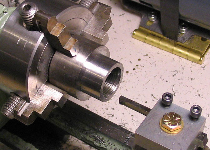
After the threading is finished, this section of the body is faced down to the length
specified on the drawing. Once that is done, the two outermost threads are cut out of the
bore to provide a guide rebate for the threads on the milling machine's spindle nose. I also
cut out 1 1/2 threads closest to the bottom of the bore, since the threading tool can't reach to
the very bottom of the bore. This will keep the spindle nose from bumping up against a
partially formed thread.
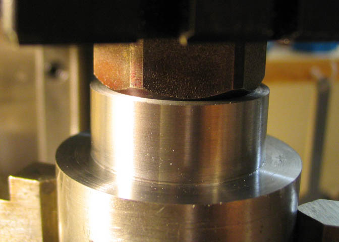
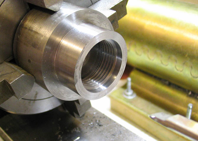
Before continuing, and without removing the piece from the chuck, the threaded end is tried
for fit on the Taig spindle nose. The edge of the bore where the piece meets the radius on
the spindle was blued and then screwed on. A shiny ring showing in the bluing shows that
the thread in the body allows it to seat properly on the spindle.
Once it's shown that the piece fits on the spindle as it should, it can be removed from
the four jaw chuck. The large end of the body is finished in the three jaw, as seen here.
Before beginning this step, I trued up the gripping portion and the face of the jaws. For
truing, I used a washer the same size as the smaller part of the body, pushed all the way
to the back of the jaws, and took a skim cut to true. Using a washer or disc the same
size as the work piece will make the chuck very accurate for that size.
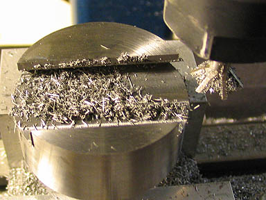
The chuck body is then put into the vise on the mill to cut the wrench flats. The first flat is cut with the piece
sitting flat in the bottom of the vise. The second cut is made using the first cut as a reference, and it is important
to get this step right, as the following steps depend on the flats being parallel and cut to the same depth in both
directions. These two flats were cut to provide a total wrench flat width of .995", as called for on the print. I
deviated from the print though, in that I only made two flats, and made them only .200" deep. I just prefer the
look of this over a hex shape.
(Some might say I was lazy, but if that were
the case, I wouldn't be building this at all...)
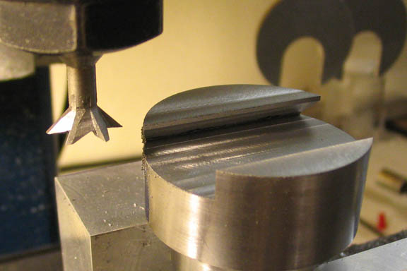
This next step is critical. The boring head body is placed on its' side in the vise, and one of
the flats is indicated in to be as perfectly vertical as possible. Nit-picking is encouraged here,
as the rest of the milling steps on this piece depend on it being right.
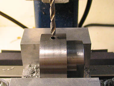
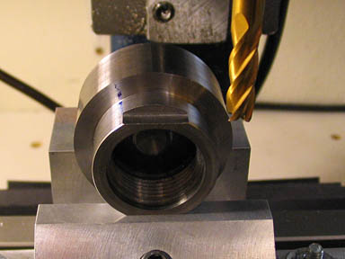
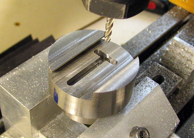
Without disturbing the setup, find the edges, and then the center line of the larger diameter of the piece
for drilling the hole for the adjusting screw. It's a deep hole for a small bit, so it needs to be cleaned out
often. After the first 3/8" or so, withdrawing the bit every .1" should do.
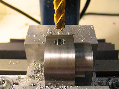
After the hole is finished, a 1/4" end mill is used to make the counter bore according to the print.
If you allow a little extra diameter for your part, as I do, you have to take that into account when
doing operations like drilling and c'-boring to a certain depth. In other words, you have to add
to the depth by whatever excess you allow for finish turning.
The rest of the milling operations on this piece are done with it in this position in the vise. The
piece is mounted with the bottom of the two wrench flats flush against the top surface of the
vise. Snug the vise a bit, tap the piece down with a soft faced mallet, and tighten up the vise
nice and snug.
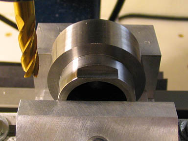
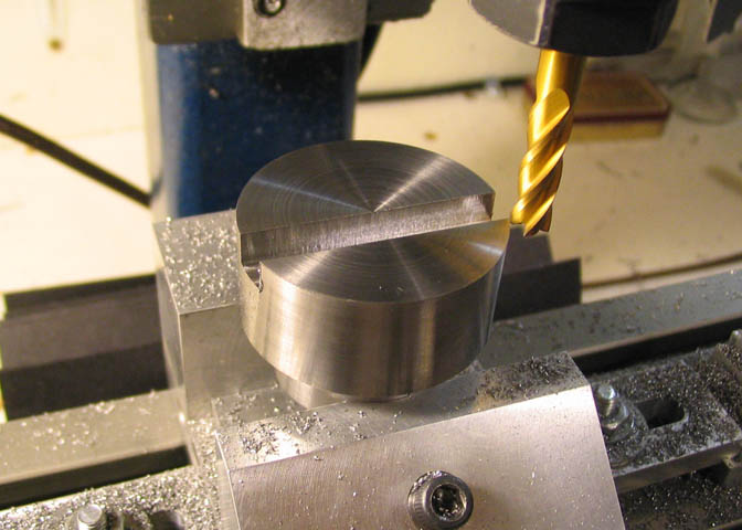
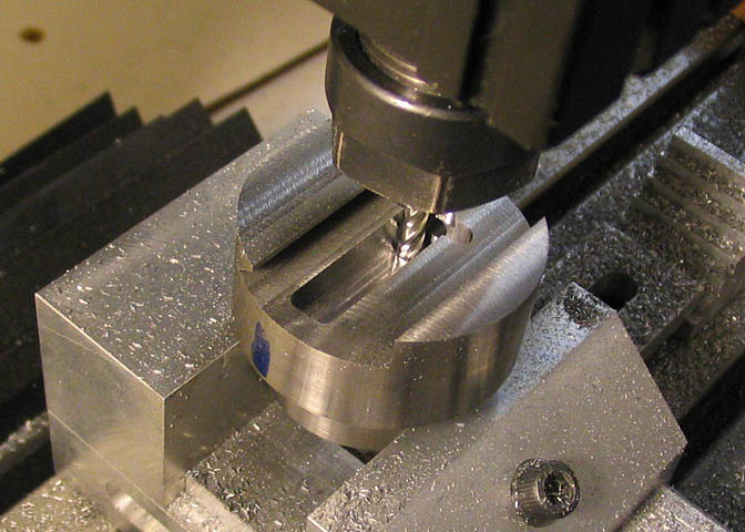
The first milling step is to cut a slot with one edge exactly on the center line. This makes
a reference point to continue removing material on either side of the center line. Note the
dial reading on the mill tables so you can refer to this starting point as needed.
The shot on the left shows the main portion of the material removed and ready for cutting the dovetail. Since
the location of the left edge of this wide slot is known (if it was cut to where the print shows), it can be used
as a reference for the dovetail cutter. The cutter diameter is also known, and by locating one side of it against
the left surface of the cut out area, the amount of in-feed needed to cut the dovetail can be dialed in.
The shot on the right shows the dovetail partially cut. Although the cutter is really sharp, it's also a little
delicate. Chips need to be cleared away after each pass, unless flood coolant is used. I don't use a flood
but do use a cutting lube when using a tool like this. An in-feed of about .010-.015" per pass is probably
about all that can be asked of a cutter of this type. These cutters must not be used to cut on the down
feed side of the cutter rotation. Cut only against the rotation of the cutter edges or you will break your tool.
When making this cut, the cutter was also allowed to take about .0005" off the bottom. When the dovetail
cut was completed, the cutter was run over the rest of the bottom area, 1) to make sure that the cutter cut
the dovetail right into where the bottom meets the angle of the dovetail, and, 2) to make sure the entire
surface of the bottom of the cut out was flat.
Note:
The tool required is a 3/4 dia 45 degree dovetail cutter. Available at any tool supplier.
Then, the last job for the cutter was a skim over the top of the piece. Again, only
about .0005" is all that's needed, and all the surfaces will be parallel. They probably
already were, but this is just to make sure.
When the dovetail is done the pocket for the nut and lead screw retainer can be milled.
The pocket is cut using a 1/8" end mill. There's a lot of material to remove for a wee
mill like this, so it takes a while. A good, sharp 4 flute end mill will get the job done
in about an hour. Blow out the chips often or the end mill will "bump"on them. Hard
on its' cutting edges.
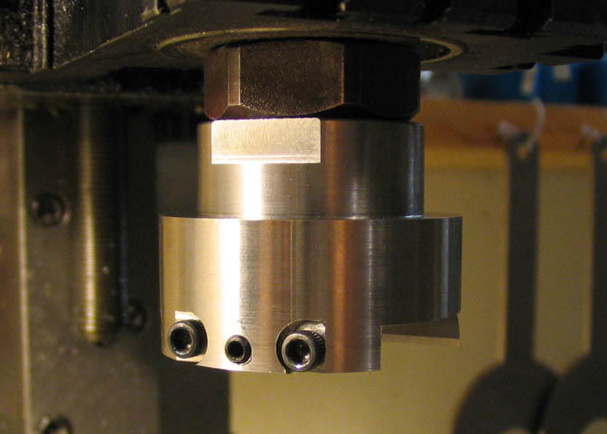
Next step is to drill and tap the holes for the gib screws.
These kind of things always happen on the last step... While cutting what was to be
the counter bore for the two outer screws on the main body, one of the flutes caught
the piece and pulled it up out of the vise. The cutter may have been a bit dull, but it's
hard to say now. By the time I heard the tell-tale chatter indicating a problem, it was too
late. This kind of stuff happens. Thankfully, the piece is not a total loss. I made a
slight change to what the prints call for in order to salvage hours of work. Also, the
mating surface that was scarred by the cutter will have to be skim cut again, just
to get rid of the bur that has been pulled up.
Oh well. At least it wasn't something really serious, like a broken tap.
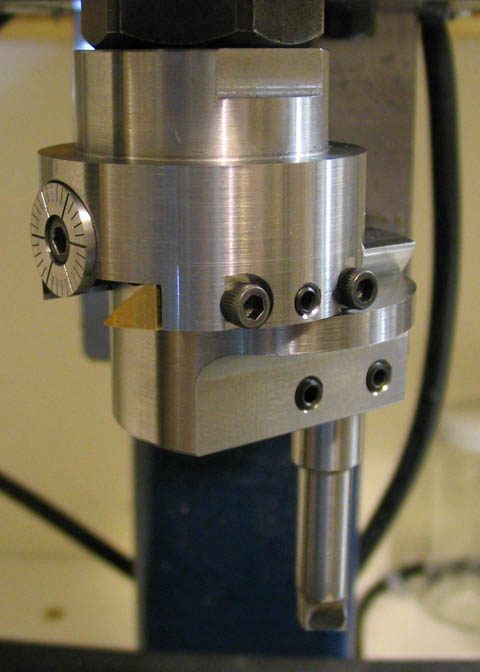
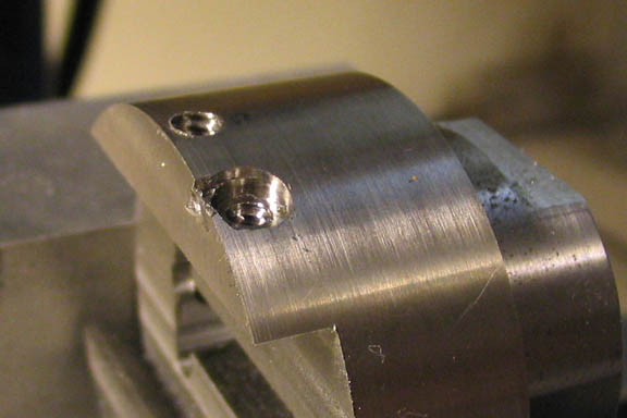
Instead of proper counter bores for the two socket head screws, a 1/4" end mill was used
to make a flat for a mating surface for each of the screws. This leaves the piece perfectly
usable, despite my little milling problem. Sometimes a person just lucks out. Sometimes
you have to start over.
On to the next part!
Go to page 2
Go to page 3
More Taig Lathe & Mill Projects
deansphotographica.com
(home page)
Copyright Dean Williams