Making a Boring Head for the Taig Mill
Part Two
The body of the boring head is now done, at least as far as it can be taken without
making some of the other parts. The next thing is the slide, which is the end of the
boring head that moves in an out to adjust tool bit for the size of hole needed.
As with the body, the slide starts as a rough turning. I began with a piece of 1 5/8" dia steel,
the same as for the body, and about 1 1/4" long. That's much longer than the print calls
for, but it makes it easier for work holding, and will be trimmed to finished length later.
The piece is turned on one end to remove the factory blemishes and faced off, then flipped
in the chuck and the same done for the other end. It doesn't matter that the piece is well
finished at this point, or even that the two halves are turned exactly the same. Most of the
larger end here will be turned away soon, but make one end the same diameter as was used
for the body piece. Eventually they will be mounted together and turned to the finished
diameter called for in the print.
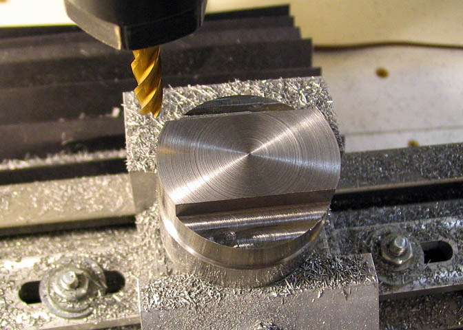
The waste end, the larger end in this case, has a flat milled on each side so the work
can be held firmly in the vise. Pick a convenient dimension and mill the two flats.
I used cuts .200" wide and .250" deep. What ever dimension is chosen, they must
be the same depth.
The piece is then turned over and tightened in the vise, making sure to tap it down with a
soft mallet as the screw on the vise is snugged up. Then the two flats that will become the
bottom of the dovetails are milled away to leave a center "island" of .815" as called for in
the drawing. The flats are .200" deep.
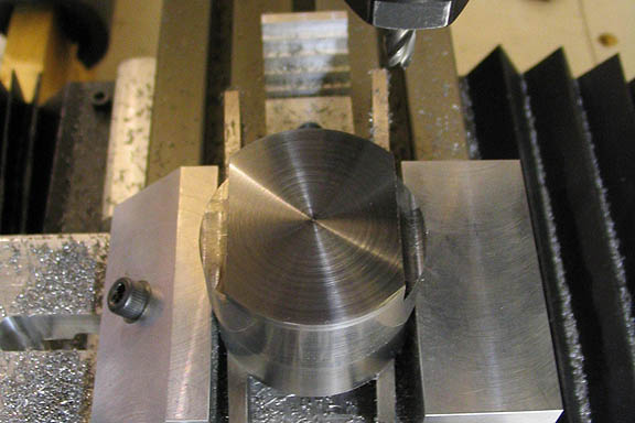
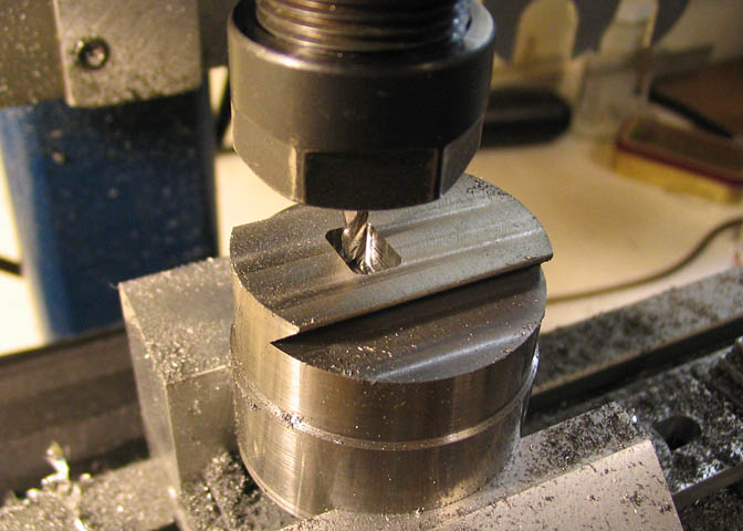
When centering the piece under the spindle, make sure to indicate off the upper portion of
the piece if you happen to have a stepped diameter as I have here.
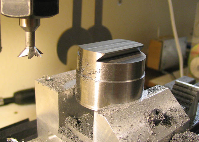
Start cutting the dovetail by taking a couple thou off the top of the piece, then crank the piece
out of the way, lower the cutter .200", and re-cut the bottom flats to make sure you have the
proper depth for the cutter, and assure both the top and bottom flats are true to each other.
Then proceed with cutting the dovetails. Follow the dimensions from the print, and make sure
to allow for any excess that has been allowed on the OD of the piece for finish work.
Before removing the cutter for the next step, place the body part onto this piece to check the
fit of the dovetail. If all is well, go to the next step.
The last step before removing the piece from the vise is to cut the pocket to receive the
adjustment nut that will go on the lead screw, which moves the slide back and forth.
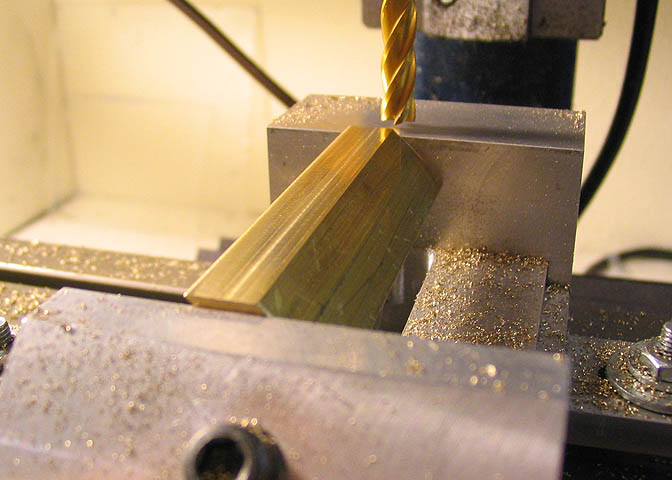
To make the gib, set a piece of brass in the vise at a 45 degree angle, and mill off one edge.
The gib is kind of small, and using a larger piece of brass to start with makes things easier to
handle. I started with a piece of 1/4 x 3/4" brass, about 2 1/2" long.
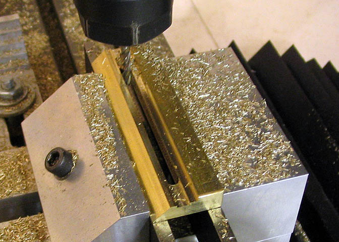
Then the gib is put on its' side using parallels to hold it above the top of the vise. A portion
of the top is milled down to bring the thickness of the gib to .200". After that the front edge
of the angle is used as a reference to dial in the depth of the gib, and a slot is cut that will
become the back edge. The the gib is sawed out of this piece. It needs to be left about 1/4"
long to leave material to clean up in the next steps.
Now the slide piece is chucked up and the end that had the two flats milled in it for holding
in the vise is turned away to bring the length of the piece to .850".
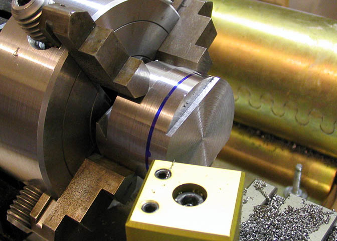
The two main pieces of the head are then assembled with the gib, and is tightened in the center
hole in the body piece to clamp them together. The body piece needs to be very true in the chuck
at this point. The slide piece cannot be dialed in, because it was originally turned separately from
the body, but the body can be brought to zero, since it is being held in the chuck that had its' jaws
trued specifically for this task. Checking it with the DTI shows less than .0005 run out.
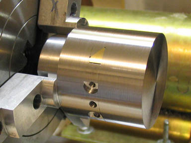
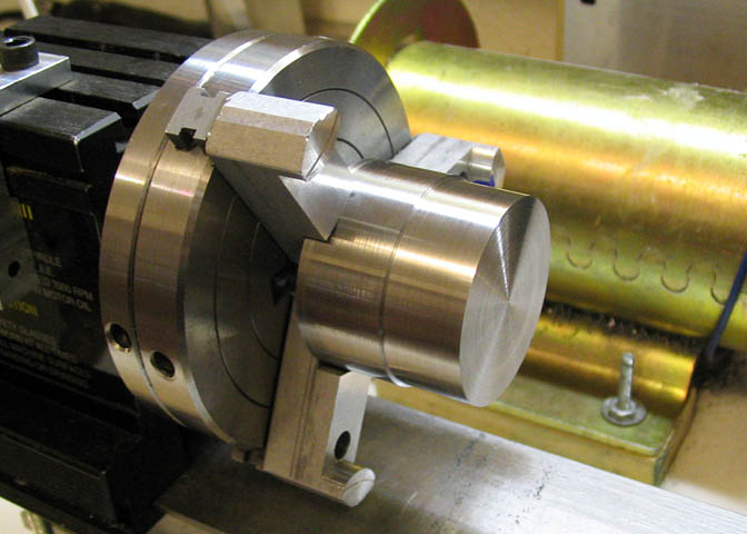
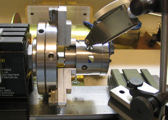
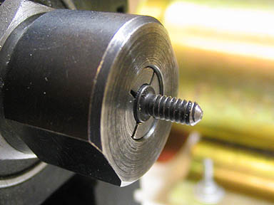
Left picture; turn the assembled unit down to the finish that suits you, for a diameter of 1.500".
Right picture; without disturbing the setup, face off the end and center drill to use as a reference later.
The two flat head screws seen in the body are in preparation for the next step.
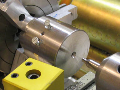
Left picture; after tightening down the two flat head screws, the set screw is removed from the center hole, and
the gib is spotted with a #35 drill bit. Then the set screw replaced and tightened and the two outer screws are
removed and the gib spotted in those two holes with a #43 drill bit. Then the gib can be removed and drilled for
a 4-40 thread. When the holes are drilled, replace the gib and tighten it down with the center (6-32) screw. Then
run a tap into the two previously tapped 4-40 holes in the body and tap threads into the gib. Use a bottoming tap
and take care not to scar the dovetail in the slide. Just get the threads started, then remove the gib again and tap
them through. This may sound like a lot of rig-a-marole, but the threads must be "in time" to allow the gib to
float in the dove tail. The center threaded hole is the one used for tightening the gib. The two outer holes are
used as the gib keepers.
On the right a 6-32 SHCS is shortened and a bit of a cone is filed on the end to serve as the gib
tightening screw.
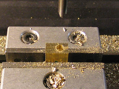
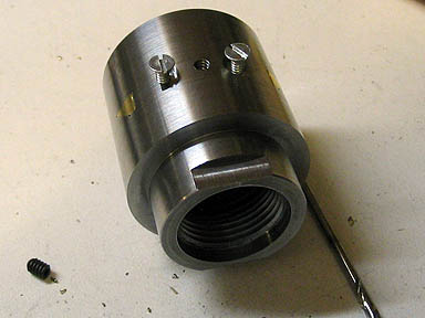
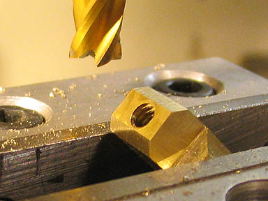
Left picture; the lead screw nut is being threaded. The basic shape of the nut is nearly square, with only a few
thousandths difference between the length of one long side and the other. The thickness is easy to discern, but
measure and mark the longer sides so the hole is put in the right place. It is drilled, counter bored, and tapped
without removing the nut from the vise.
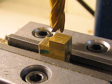
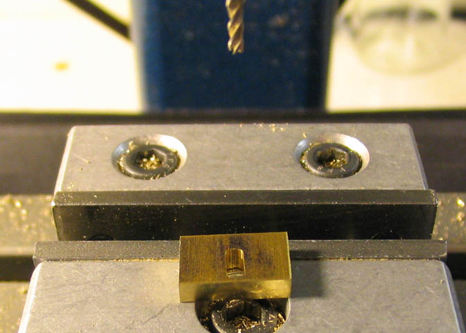
Right picture; one of the flats being milled off the nut. Note that the flat goes on the opposite
end from the counter bored part of the hole.
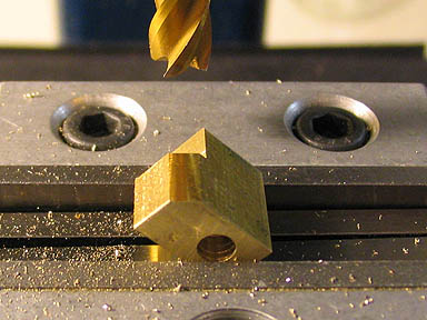
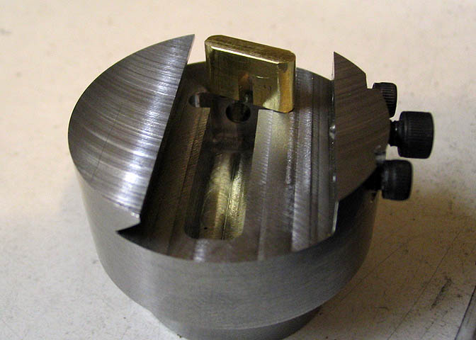
Left picture; I couldn't figure out what this 45 degree flat was for, until I went to put the two halves of the
boring head together. Then it became clear. Without this odd flat milled away, the boring head can't be assembled.
Right picture; The last two 45 degree flats are milled on the end of the nut that has the threads showing.
The angles on this piece are set up using a simple small adjustable leg protractor, which will provide
all the accuracy needed if used carefully, (for this part, at least).
The lead screw retainer is made from a 1/8" thick piece of brass sheet. Once the basic
rectangular shape is milled out, the edges of the piece are found and the inner end of the
slot is located. The radius called for is problematic for manual mill users. It is noted as
.041', which would mean a .082 diameter end mill is needed. It's simply a matter of cheating
a little, using a 1/16" end mill, and off setting the cutter .010" each side of the center line
of the cut. The radius in the extreme corners of the cut will be slightly tight, and may need
to be touched up with a needle file when fitting the piece to the lead screw.
Since the part was being held with what would be the open end of the slot against one of the
vise jaws, the cut can't be completed without turning the piece on end after making the
initial slot. After tightening it it the vise with the edge pointing straight up, the side of
the piece is found, and the same amount of travel as for the first cut is dialed in. Then the
cut is completed.
Another way to do this in one set up is to use a sacrificial piece of brass between the piece
and one of the vice jaws. Then the cutter can be run past the edge of the piece to
complete the slot.
Here is the finished piece shown sitting above the slot it will occupy. The radii on the ends
were finished in using a file.
Go to page 3
Back to page 1
More Taig Lathe & Mill Projects
deansphotographica.com
(home page)
Copyright Dean Williams