Headstock Index Plate and Speed Reduction Pulley
(or, killing two birds with one...lathe)
I've been meaning to make an index plate for the Taig lathe headstock for a while, and
finally got around to it. I have a divider, and a stand alone indexer, but sometimes just
being able to index right on the lathe headstock without removing a workpiece between
operations would be very handy.
The index plate attaches to the headstock pulley, and I've seen a number of examples on
the web. I thought while I was at it, I would give it a little twist and make the plate dual
purpose by turning a pulley groove into the outside diameter. The plate is somewhat larger
than the largest pulley groove on the factory pulley, so it would provide a bit of a speed
reduction, along with the indexing function.
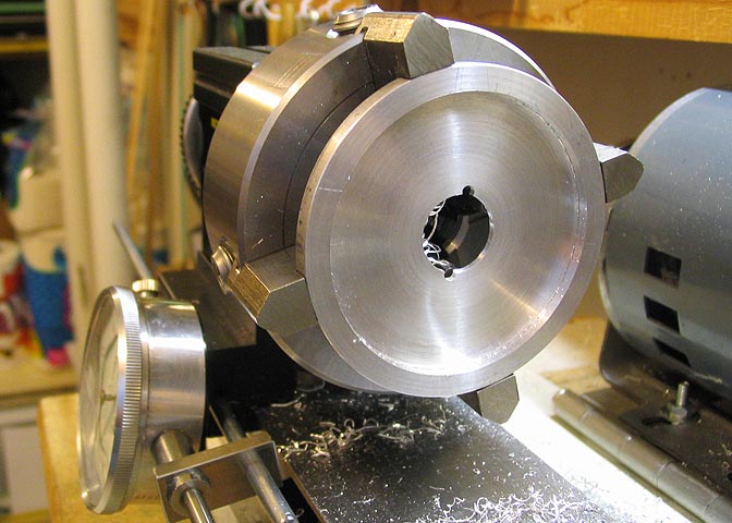
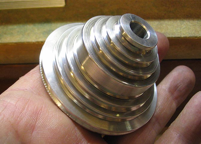
I had a piece of aluminum that I had cut from a rod from another project. It's about .18" thick and
2.75" dia. A hole is bored in the center of the disc large enough to fit over the headstock shaft.
Then the large recess is bored out to a diameter that will be a close (snug) fit over the large end
of the Taig pulley. There is a bevel on the end of the Taig stock pulley. The recess must be
deep enough to go past that bevel and fit close around the body of the pulley, but not too deep
or it will interfere with the belt in the adjacent pulley groove.
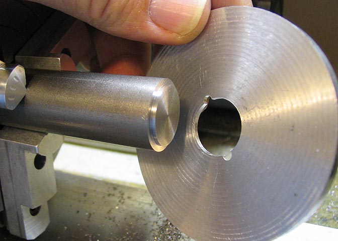
An arbor was turned up to fit my dividing head on one end, and with a shoulder on the other end
that will be a close fit with the hole in the index/pulley disc. Then the arbor is drilled and
tapped in the end with the shoulder to take a cap that will hold the disc tightly.
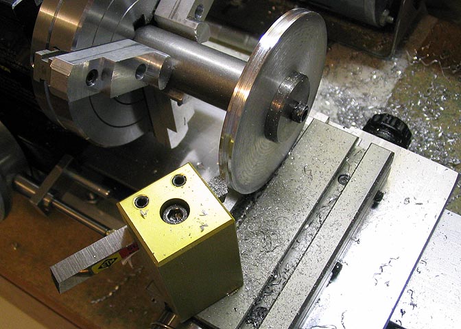
The disc is mounted on the arbor, and the groove turned into the outer edge of the disc.
I used the Taig drive belt to check the groove in the disc, and kept cutting 'til I got it right.
The disc was too large to swing over the cross slide, but fit into the T slot of the slide.
This way I could still cut the groove. I could not move the carriage side to side without the
disc rubbing on the sides of the T slot, so to cut the groove, I took a small bite out of
one side, then loosened the tool post to adjust the cutter right or left, and took another bite.
I got a little chatter, even taking small bites, but a triangle file made it smooth enough
that it will not damage the belt.
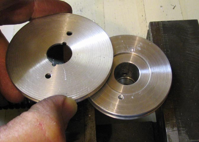
Once the groove is cut, the recess in the disc is fitted over the Taig pulley and mounting
holes are drilled and tapped. By the way, the two slots you see in the disc are not needed.
They are just left over mounting holes from a previous project.
Now the disc is remounted on it's arbor and screwed onto the dividing head to drill the
indexing holes. 60 holes, in this case. For a write-up on this dividing head, check out
the Dividing Head project.
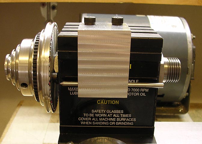
Now the drilled pulley disc is fitted to the stock Taig pulley.
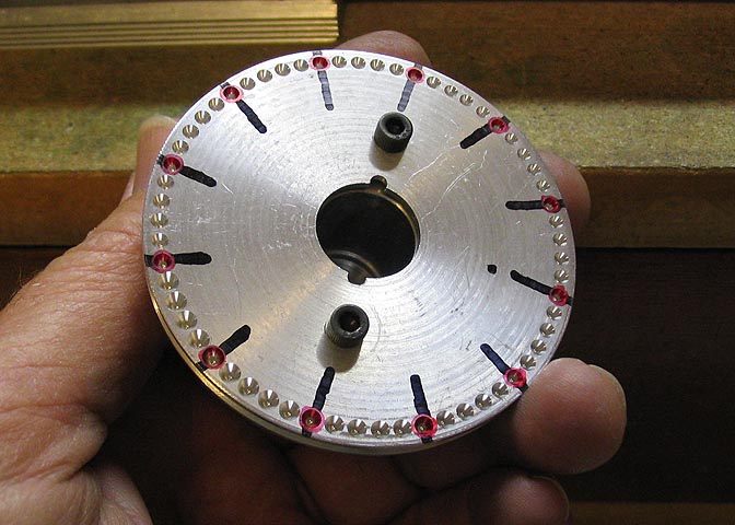
And a view from the back side. I used marking pen to mark each 5th hole.
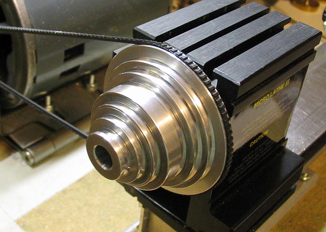
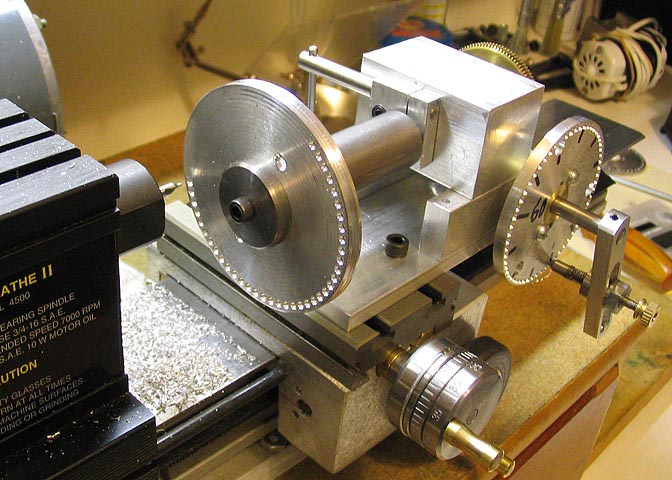
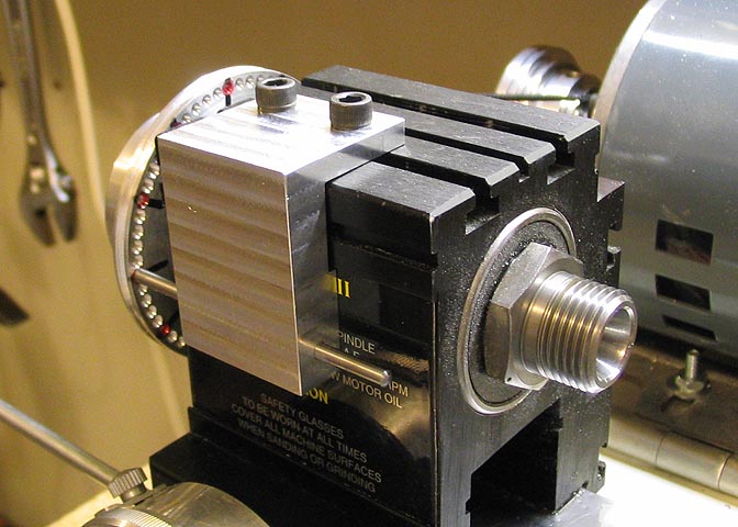
This shot shows the mounted assembly and belt. The new larger pulley
reduces the lowest speed by about 100 rpm. Not a lot, but sometimes
it's just what you need.
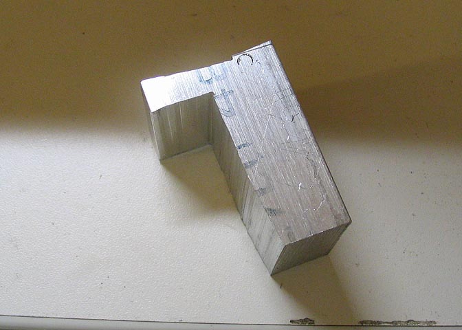
Now I need a mount for an indexing pin. I started with a piece of square
aluminum billet and cut out the basic shape with a hacksaw. Took a while,
but still faster than milling all of this material away. As you can see, I sometimes
have a hard time cutting a straight line!
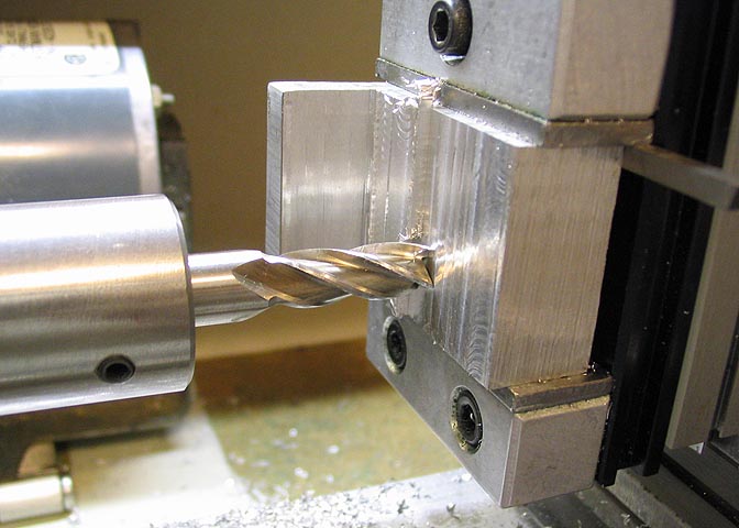
The piece is mounted in the Taig milling accessory and everything is milled
square, and to an approximate size. A holed is drilled and reamed through
the thick section of the piece for the indexing pin before the piece is milled to
final size, and then the face of the piece that will mount against the headstock
is milled down until the pin will engage the holes in the index plate properly.
The finished item mounted to the headstock.
That's it.
More Taig lathe projects
deansphotographica.com
(home page)
Copyright Dean Williams