A Fairly Simple Dividing Head
I made a simple indexer some years back. It works well, but I can only divide in numbers that
are already drilled into an indexing plate. I have a number of index plates for mine, but I often
find a division is needed that my premade index plates will not provide. A simple dividing head
will make some of my shop tasks easier, and besides, I want one.
I made this one from a picture I saw in Tony Jeffree's Taig book, (thanks for the ideas, Tony.)
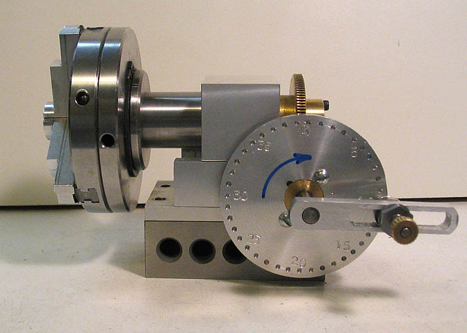
First, a shot of the finished item. It's not fancy, but works quite well.
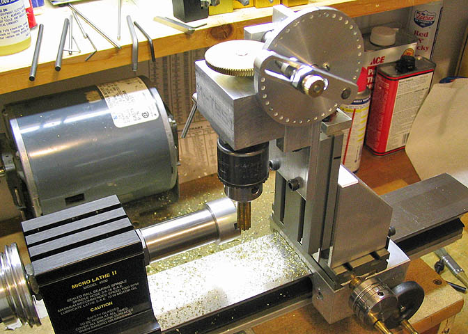
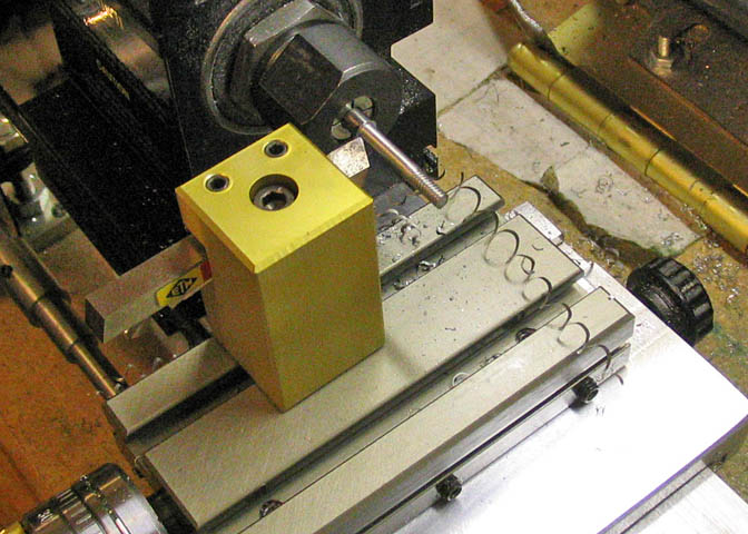
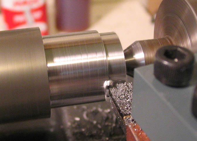
Here it is shown on my Taig lathe, doing what it does. In this case, I'm making a pinion (gear)
for an old Ingraham clock movement I am repairing.
I didn't make up any prints for this, just thinking it out as I went. The photos here may offer some
ideas for someone interested in making a similar item. I'll just put the photos in a kind of logical
order with comments that may apply.
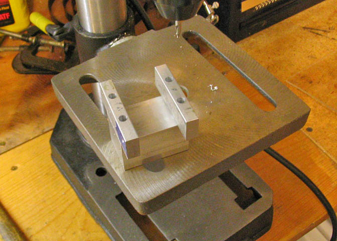
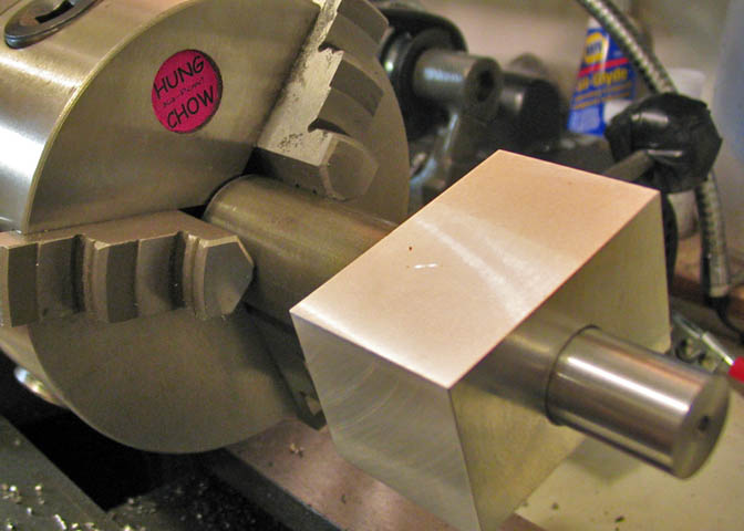
Squaring up the ends of the main body with a fly cutter.
And squaring up the ends of the blocks for the worm shaft.
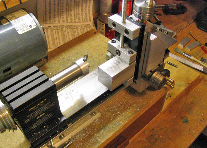
The worm shaft blocks mounted to the main body.
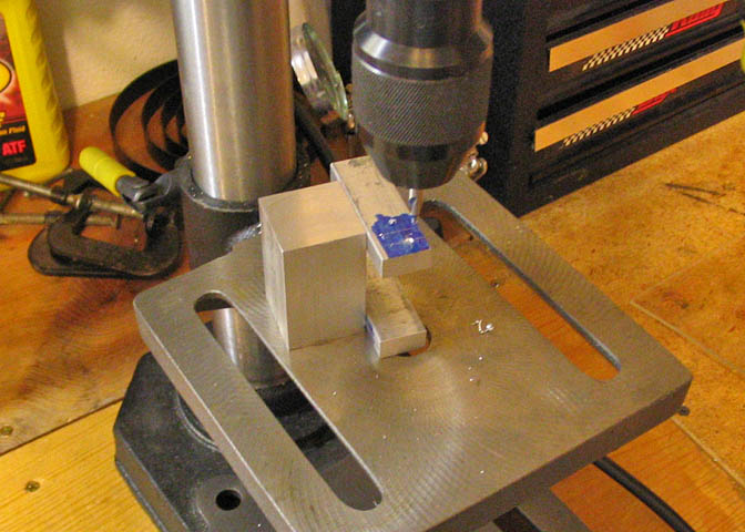
The bearing holes for the worm shaft are drilled and reamed for the proper size of the shaft.
In this case, 1/4".
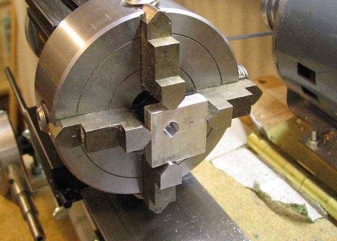
The main body is drilled through and reamed to fit the shaft for the worm gear, then partially
bored to a depth that is suitable for the end arbor of the main shaft. Since the boring opera-
tion here doesn't go all the way through the main body, I circled the side that needed boring
so I wouldn't bore the wrong side.
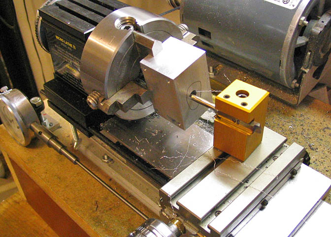
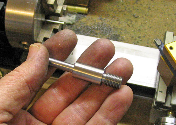
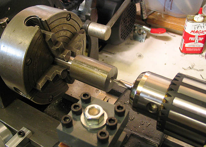
Here, the main shaft, which is 1/2" CRS, has had a length turned down to take 3/8-24 threads for
a drill chuck. The end closest to the chuck has had a landing turned into it, with a small relief where
the threads will end. This will let a drill chuck or a threaded arbor mount up tight to a true surface,
similar to the way the Taig chuck mounts to the spindle.
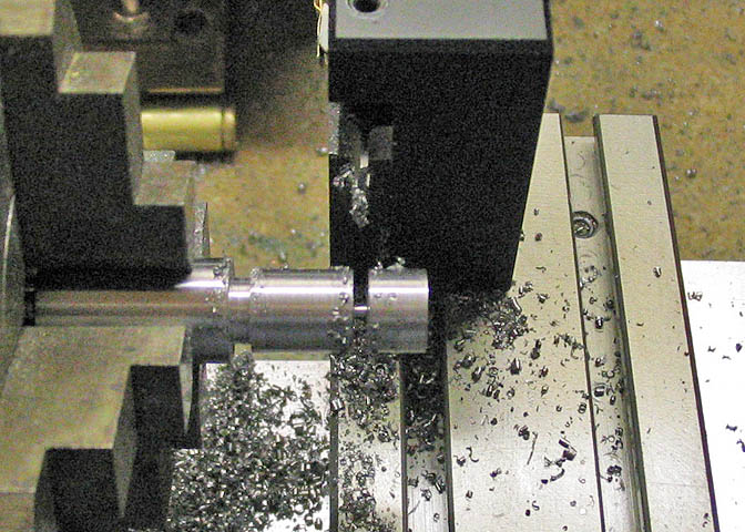
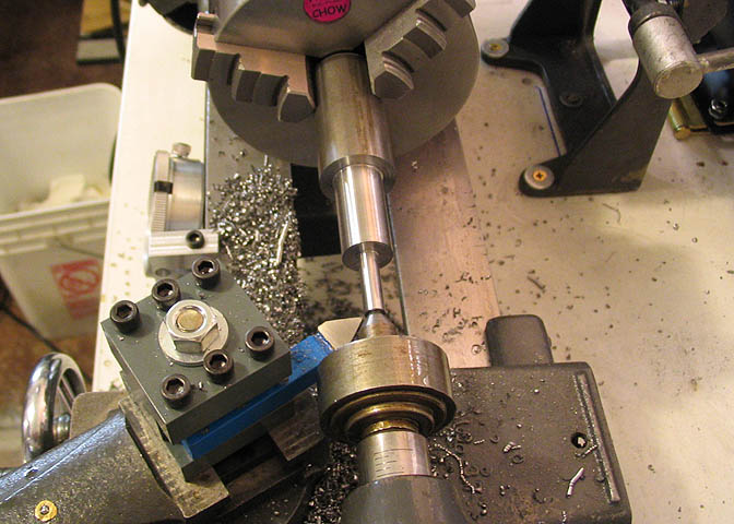
The excess has been nearly parted off, and I stopped so I could take this picture, with a mind for
the following;
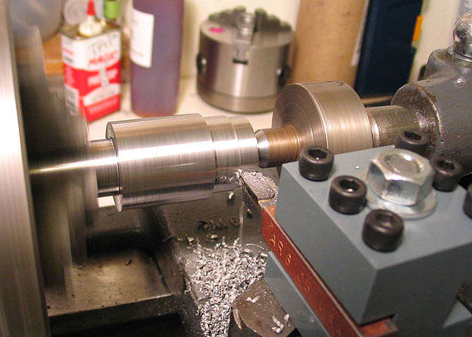
Many people have trouble parting-off, and if things aren't set up just so, it can be a problem. The piece
shown is full strength CRS, not leaded steel. This parting cut only took about 10-15 seconds with a spindle
speed of about 550 RPM. It will really help when parting-off if you have the parting tool at exactly 90 degrees to
the work piece, (or parallel to the face of the chuck, same difference). Your parting tool needs to be sharp!
Also, some type of lubricant is a real plus. For this cut, I used just two drops of Tap Magic.
It's a fast cut, and that's all it takes.
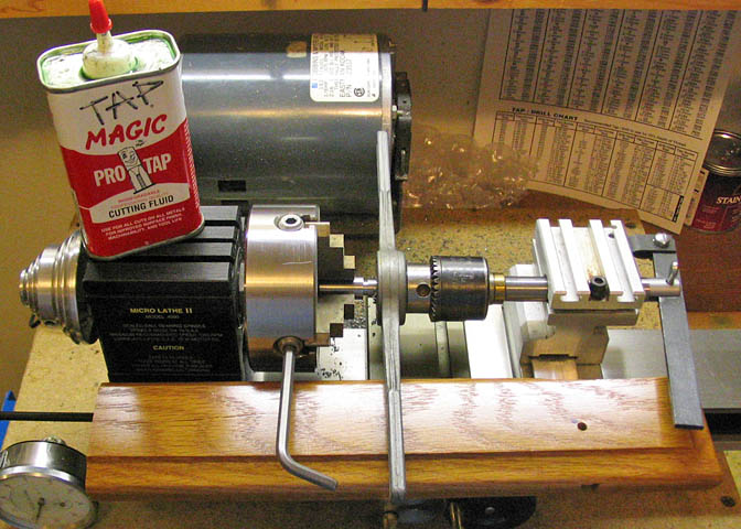
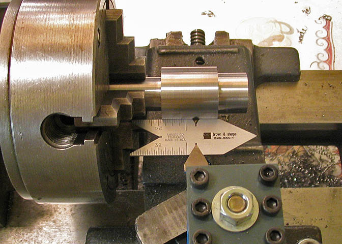
Now that I have the arbor to the proper length, the end is threaded for 3/8-24. I have a die holder
that mounts to the Taig tail stock, but the only die I have in this size is six sided, which won't fit the
Taig die holder, (it takes round dies). So, I'm doing it the inconvenient way, with a die handle.
I run the tail stock drill chuck, (with it's jaws fully retracted) up against the die to help keep the threads
square while threading. Also, a little Tap Magic helps. CRS is hard, and threading will sometimes
chip it. A good lube will usually help in preventing this problem.
After the threading is done, the work piece is reversed and indicated in on the four jaw chuck.
Then the small end is turned down for a running fit in the main body.
This is the finished main shaft.
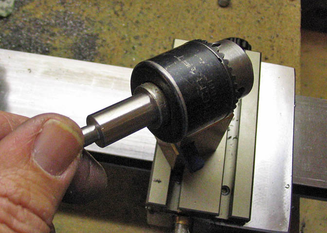
And the shaft with a chuck mounted. It can also take threaded arbors for special applications.
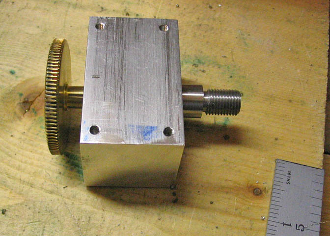
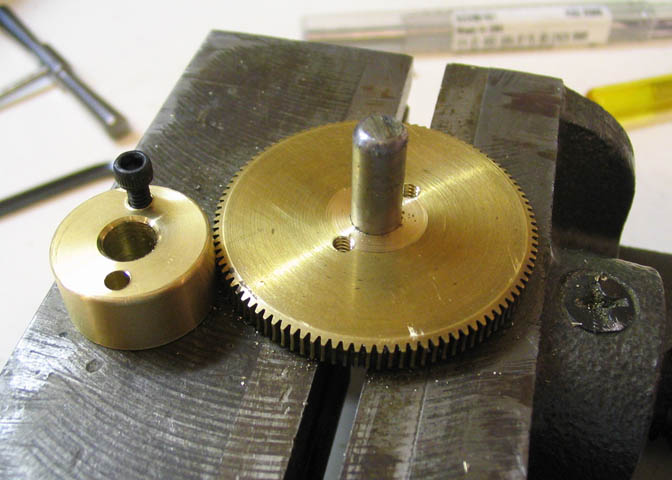
The main body complete.
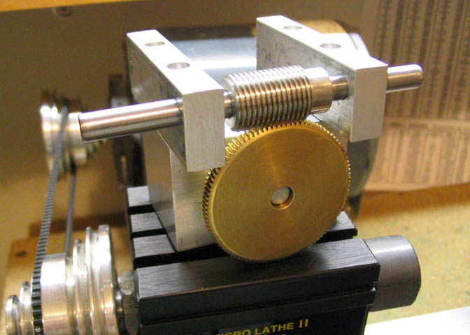
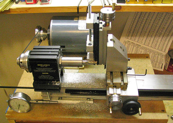
And the first assembly fit up.
Yes, that's a lot of teeth on the gear. I used what I had on hand. I got this worm and gear a while
back for $5. I had to make something to use it. It's 100:1.
30:1 or 60:1 would make better sense, but I can do a lot with this and a 60 hole plate. For
instance, I can make more plates.
This is what will become the brake for the main shaft.
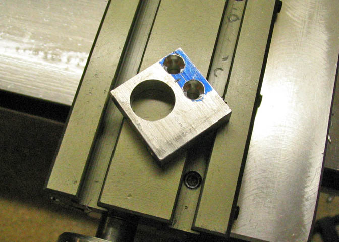
After boring a whole the size of the big end of the main shaft, mounting holes are drilled to match
holes in the main body. Looks kinda like Mr. Bill. Oh Noooo...
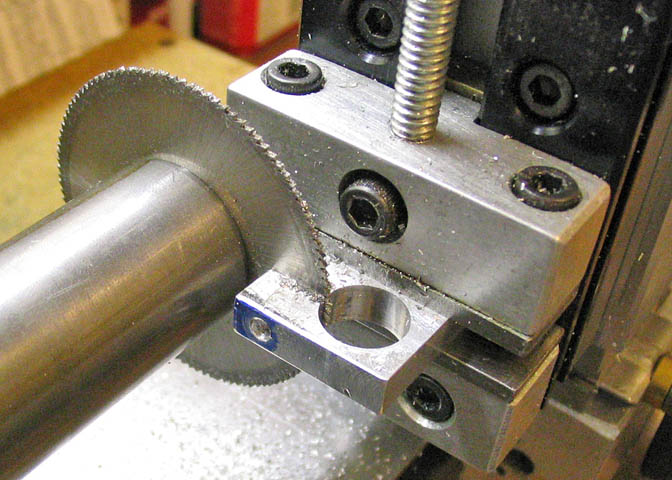
Another hole is drilled and tapped for the clamp that will tighten the brake, then a slot is cut
so the brake can flex and close against the main shaft.
The end of a piece of drill rod is turned down and threaded for the brake shaft.
The lock shaft is then turned to the proper length behind the threads so as to fit in the brake. A
shoulder at the end of this cut is left and that diameter continues for the rest of the length of the shaft.
The shoulder will bear against one surface of the brake to close it as the shaft is tightened.
The shaft is of drill rod.
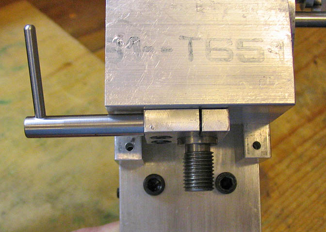
Here you can see how the completed brake assembly fits to the main body.
Next a bushing is turned and threaded for the indexing pin.
Here is a detail shot of the index pin with it's bushing.
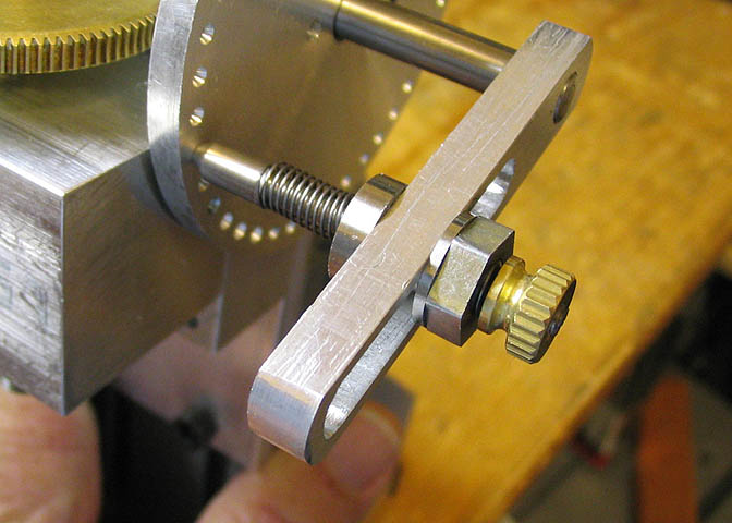
Another shot of the index pin assy. Easier to see the indexing arm in this one. The indexing pin
bushing, along with it's pin, can be loosened and moved in the slot in the arm to adjust for plates
of different sizes.
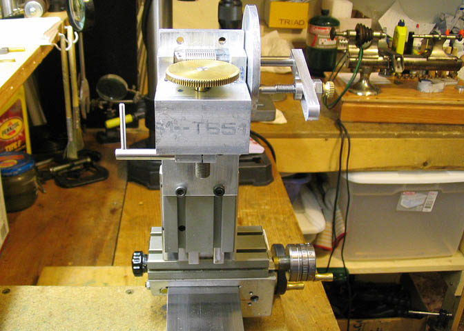
A plate is attached to the back side of the indexer, as seen in this shot, with six mounting holes
matching the Taig slide. Only four of the six hole are used at one time, depending on how high
the divider needs to sit on the milling column.
That's it.
Dividing Head Rebuild and Update
After using this dividing head for a few years, and doing a lot of projects with it, I decided it needed
a bit of an upgrade. It's done good work just the way it is, but I want it to be able to take the standard
Taig spindle chucks for transferring work from lathe to mill while leaving it in the chuck in its original
setup. This way, if I want to cut gears on the mill, I can start off by cutting the gear blank using either
the three jaw or four jaw chuck on the spindle of the lathe, then unscrew the chuck along with the work
piece still in it, and transfer it directly to the dividing head, maintaining a concentric set up.
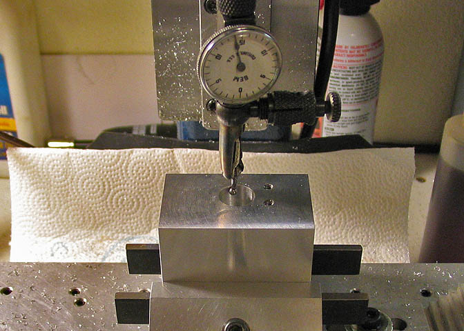
I started by taking the little dividing head to bits, putting the spindle block in the mill,
and getting the spindle bore dialed in.
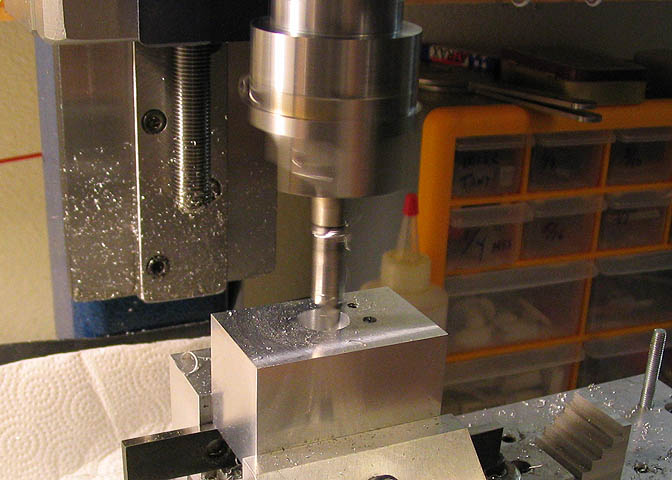
Then bored it out to .625" with the boring head. That's about the largest it can go and still have enough
meat to be sturdy. It's quite a bit larger than the original bore and spindle, which were .470".
Now, I need to make a new spindle for the dividing head.
A piece of 1" stock is chucked up in the "big" lathe, (the 6" Atlas), and a spigot is turned down to
about .600" on one end. This spigot is for work holding at the moment, but will be turned down
to .250" after the bulk of the material has been removed for the spindle running surface.
Behind that diameter, a length is turned just short of the depth of the bore in the spindle
block, and to .6245" dia. This will fit the new larger hole in the dividing head block.
Then the spindle block is tried for fit. Got lucky and hit it right on the first try. The fit is nice and close, and
it almost wants to squeak as it goes on. This part of the spindle is slightly shorter than the block that it runs
in, so the spindle can be adjusted some for end play.
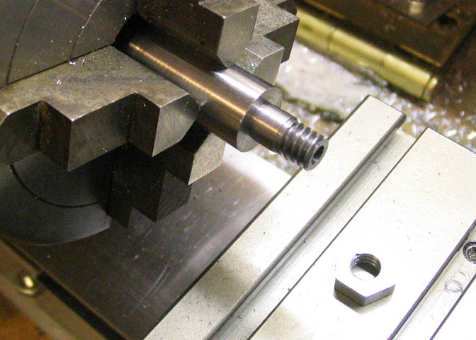
Once all the hard turning is done in the middle of the shaft, the spigot is turned down to .250, which is the
bore of the worm gear. You can see in this picture that it isn't very substantial once it's been turned down,
and that's the reason for leaving it big while taking the heavier cuts in the middle of the shaft.
I used a threading tool to get in close to the live center, and canted it sideways a bit so it could cut to the
corner where the smaller diameter meets the larger one, and then back it out with the cross slide to face off.
What is needed here is a half-dead center, but all my centers for this machine are either live, or all the way dead.
Now the three jaw is replaced with the four jaw chuck, and the piece is dialed in nice and close
for work on the other end.
The end is faced off to bring the unfinished bit to length, then center drilled for the live center.
It's not very long at this point, but still, I use a live or dead center whenever I can. There's nothing
like having both ends supported if it will fit in with your plans.
After facing, a skim cut is taken off the length to clean up the factory bumpy parts, then a length is
turned to mimic the length and diameter of a Taig lathe spindle nose, since I will be using Taig chucks.
Getting set up for threading.
Compound set at 29 degrees, tool tip set to 90 deg with the work. The tool tip is then run up close to the work
and the cross slide set to zero. This is home base, and lets you run the cross slide in and out when running
the tool tip back and forth with the carriage, so you don't have to mess with the compound except to dial in
another cut. Set the cross to zero, and you won't loose your place.
An old machinist beat that into my head. Someone else probably beat it into his head sometime before WWII.
His name was Jack Cuddy, and he was a patient guy, and a nice man to have for a friend. I wish I remembered
everything he tried to teach me. I wish he was still around to ask..
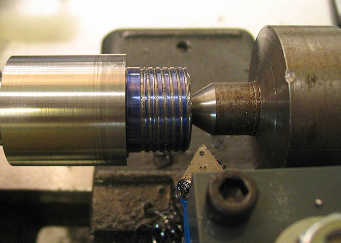
Cutting the threads. The above shot is a number of cutting passes into the job. The first cut I take when
cutting threads is always a very fine scratch on the blued shaft. Then it is checked with a thread gage to
make sure I've got the correct gearing set on the lathe. This way, if I goof with the gearing, I haven't ruined
the work. After that, get serious and dial in a real cut. About .005" for the first cut on this 3/4-16 thread,
and progressively less as the thread gets deeper. Always dialing in the thread with the compound slide.
How deep to take your cuts depends on lathe size, how far the piece sticks out of the chuck, whether it's
supported on the end or not, the diameter of the work piece, and the coarseness (or fineness) of the thread.
It's a judgment call, for sure. When in doubt, take finer cuts, or run a test piece to see how the
equipment will act for the given situation.
Threading oil is usually dripping off my threads when cutting them. I had just run a brush over these to clean
off the chips for the picture. Normally, I use the kind of of cutting oil that is made for pipe threads. The kind
of stuff that smells sort of like sulfur. It has sulfur in it, so that would probably explain it.
Sometimes I use Tap Magic, which works pretty well, too.
Note in the shot above, a bevel has been cut on the end of the shaft. It was done before beginning
the threading job. Makes for a nicer thread start, and helps that first thread find its way into the first
thread of the chuck, or fastener, or whatever you're going to put on that thread.
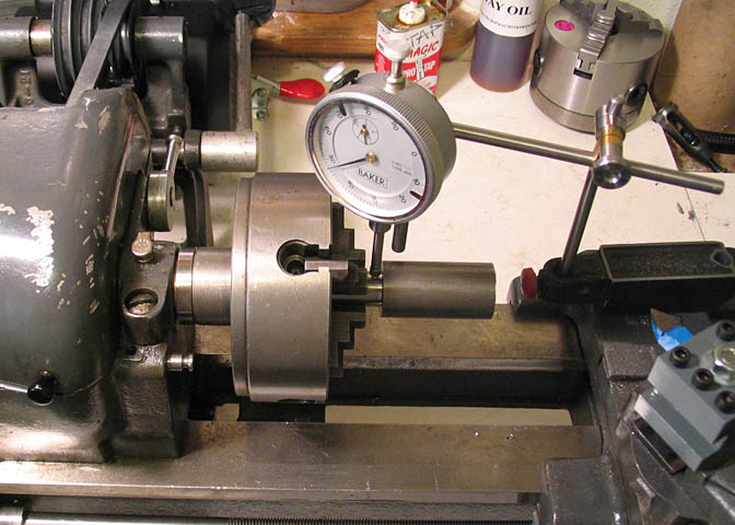
When the threads started looking close, I tried one of my chucks after each shallow pass until it went
on without any tight spots. Running the DI on the outside of the chuck shows runout of a bit less than a thou.
There are thread depth gages made for checking critical threading jobs. Some are built into a
micrometer. Some are a type that uses precision ground thread wires, which fit into the threads
and are then measured with a mic. I was taught how to use the latter method by the same fellow
who showed me a lot of things, but I've forgotten through lack of practice. Shameful. The threads
I cut are all "cut-and-fit", which is probably all that's required in most home shops. If you have to cut
threads for a job to match a print with a thread spec though, it requires proper measurements.
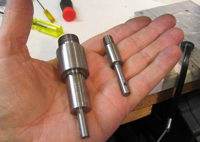
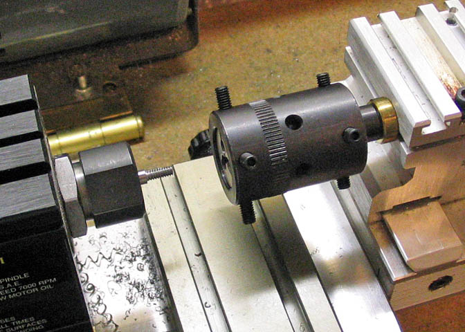
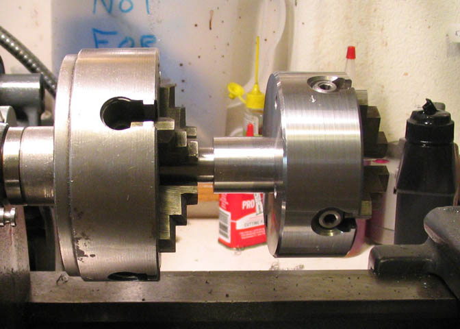
This is the original spindle, along side the new one. Much more hefty duty-ish.
Going to the worm gear, now. It had been mounted on the other spindle with a screw through a thin collar
that came on the gear. It needs something more substantial, and, it needs a means of getting rid of end play in
the spindle, so, it has to be able to move back and forth on the spindle a little.
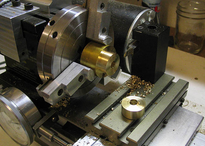
I cut a couple of collars from brass stock. One to act as a thrust washer for the end play situation, and one that
will be the new mounting collar for the gear.
Here, the original collar can be seen, and it's about to be cut off.
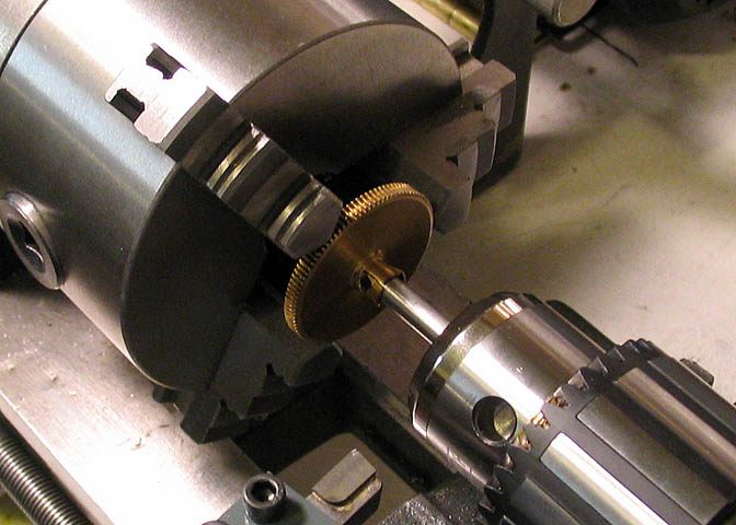
To set up the gear in the three jaw without having the face of it wobble, it's put on a temporary arbor and
held in the drill chuck. Then the lathe chuck jaws are snugged down gently. Not tight enough to smush the
gear teeth, but enough to hold it for cutting.
Once the old collar is gone, the new one is lined up with the gear using an bit of round stock, and the tap
holes are drilled through both pieces. Then the holes in the collar are opened up for clearance on
the 4-40 screws that will be used.
It would be nice to counterbore the holes for the screws, but when I put my counter bore pilot in one of the
holes to check, it looked like there would just not be enough meat in the collar. The C'bore would come
through the side. That's called lack of foresight. I should have made the collar a little larger in diameter.
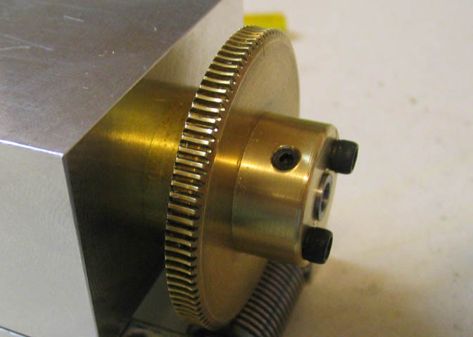
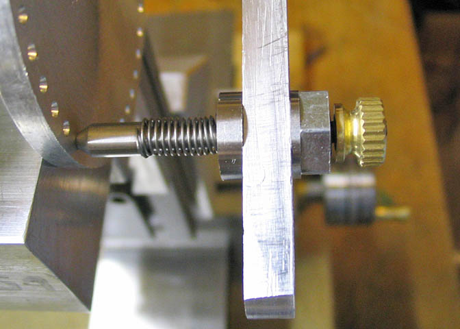
This shot shows the back end of the assembly buttoned up. Thrust washer on the inside, then gear, and lock collar.
That's it. My old friend is ready to get back to work. Almost like having a new tool.
Thanks for looking,
Other (Taig) lathe projects
deansphotographica
home page
copyright 1998-2010 Dean Williams