Filing Rest
This little item is sized for the Taig lathe, but can easily be scaled up for larger lathes.
It's intended use is for filing flats on round stock held in the lathe headstock, as you may
need for making hex head flats for a wrench on an otherwise round piece of material.
Also handy for filing a nice set screw flat or square ends, and etc. It is adjustable so you
can raise or lower the level of the file for making different sized articles. A file is used
across the rollers, and as material is removed from stock held in the chuck, the file
eventually ends up resting on the rollers, and no more material removed from that place
on the stock work piece.
I started with a piece of 1"x1"x .125" aluminum angle iron. If I were making this again, I would use
HRS rather than aluminum. The one I made works perfectly well, but could be a bit more rigid,
so steel would be a better choice.
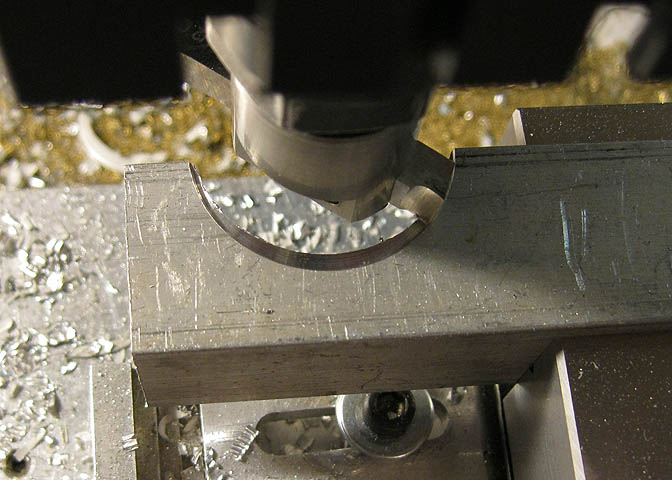
Using a flycutter or boring bar, a number of cuts were taken to produce a semi-circle in one flange
of the piece of angle. The ear at top left ended up at .3" wide, and the semi-circle a diameter of
1.375". The piece will eventually end up being flat, but starting off with an over sized work piece
in the shape of an angle iron gives you a lot more work holding options.
Once the semi-circle was cut out, I took a swipe with the flycutter, just to clean things up a bit.
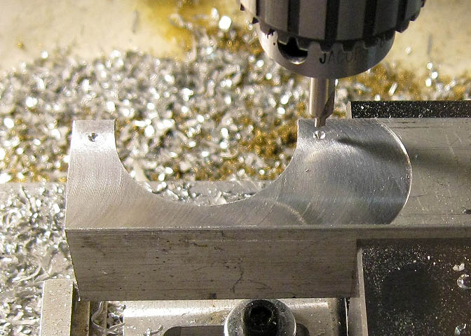
Then a center drill is used to spot a couple of holes centered in what will be the two roller
support flanges.
Then the two holes are drilled and tapped for 6-32. After reading the article through, you may
be tempted to simply drill these two holes through to pass the roller shafts and just use a nut on
the other side to hold it. I though about that too, but decided it would almost certainly lead to
loose and wobbly roller shafts. Tapping these holes as well as nutting the shafts on the other side
will make for a much steadier setup.
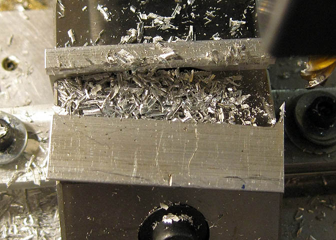
Now the piece is cut off the parent metal for finished length of 2". The piece is then clamped
on the part that has the semi-circle cut into it, and the remaining flange of the angle iron milled
off to end up with a flat piece for the project.
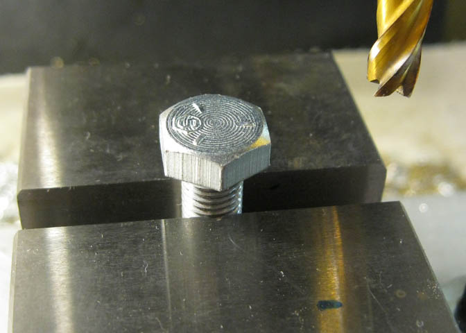
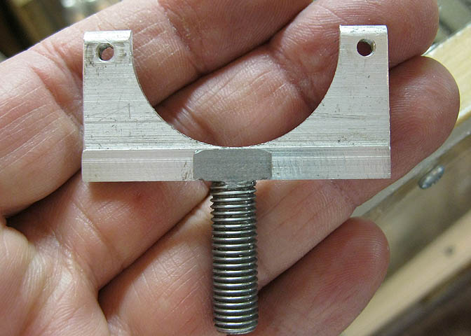
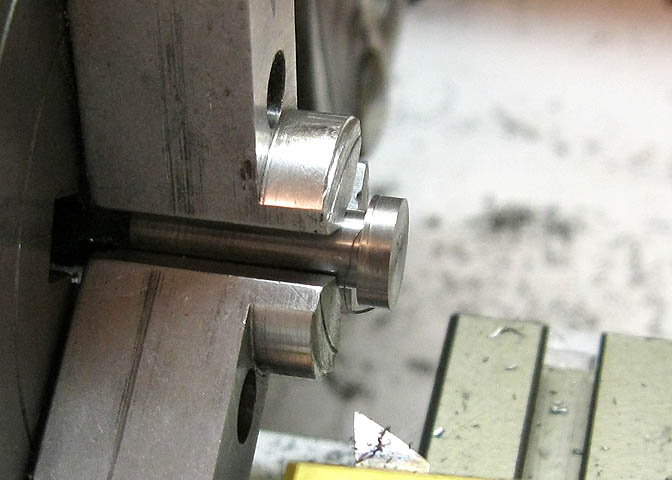
Now for the support stud. Starting with a 5/16-24 x 1" lg. hex head cap screw, mount firmly in the
vise with two of the hex flats perpendicular to the X axis of the milling machine.
Mill off the other four flats, leaving just the two as shown in the picture above.
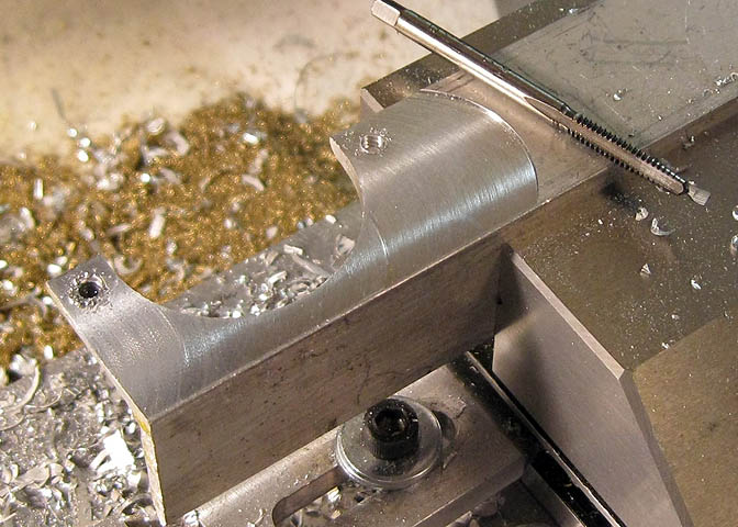
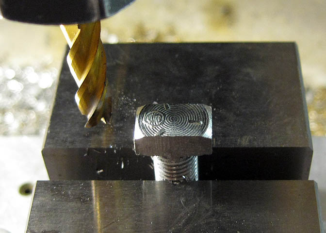
With a 1/8" end mill, cut a slot down the middle of the screw head as shown above. Make
the slot just deep enough that it comes down to where the main shaft of the screw threads start.
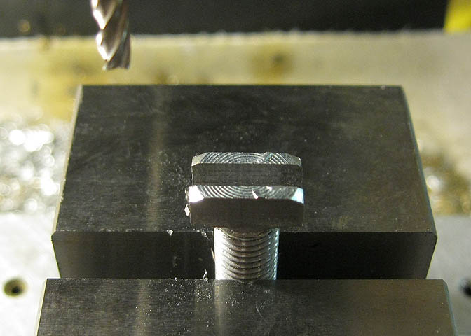
Now you can see how things are going to mate up.
Center the piece with the semi-circle in the slot in the cap screw, and tap it down flush.
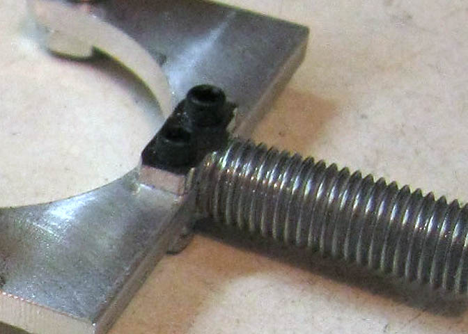
Then drill two holes through the complete assembly for 2-56 cap screws.
The next thing is the roller shafts. These are 3/16" drill rod, two pieces needed. Thread one
end of each for 6-32 x 1/4" long. Thread the other ends for the same thread, and long enough
to take hex nuts. The main body of the shaft is .875" long, not counting the threaded ends.
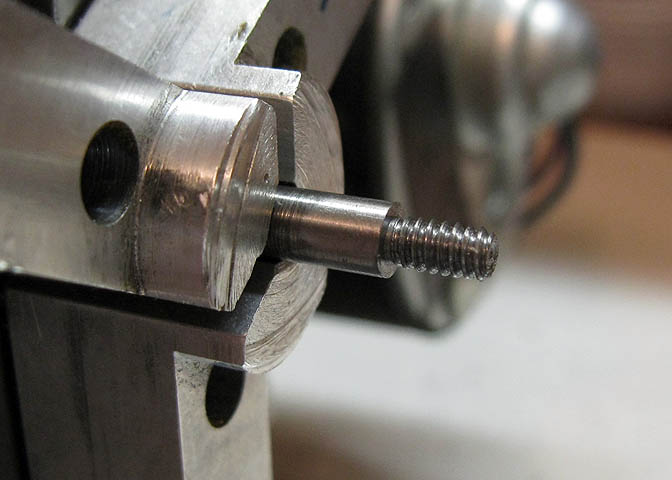
For the two rollers start with 3/8" drill rod. Turn down the end section to 1/4" diameter for
a length of .75". Check the width of a few of your files at this point to make sure they will
fit this dimension. You may have to make this cut slightly longer.
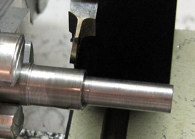
Now cut off each piece, leaving enough of the original 3/8" diameter to finish off for a
shoulder .1" wide. Total length .85". Drill and ream each piece down the center for 3/16".
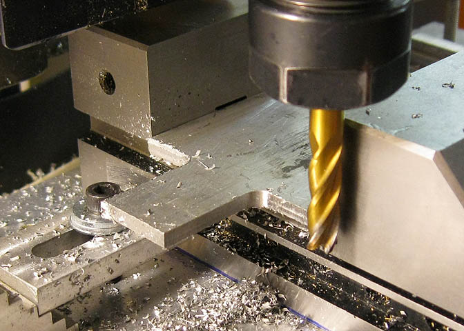
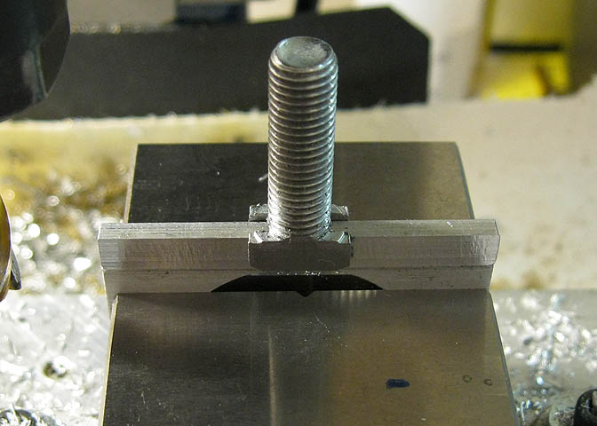
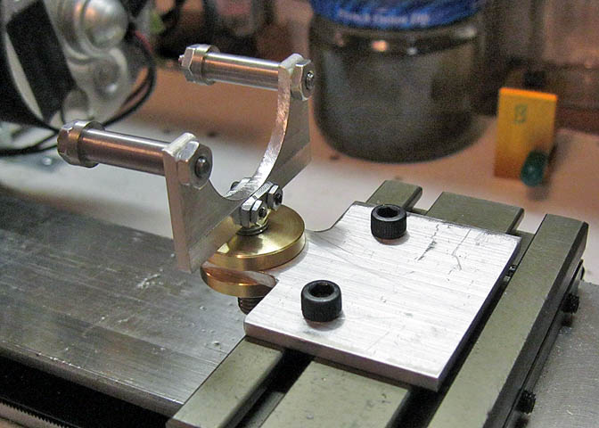
The base is made from 1/8" thick aluminum plate, 2" wide, and 2 3/8" long. The narrow part
being milled in the shot above is 3/4" wide and .8" long, centered in the piece. Drill a hole for the
threaded 5/16" shaft in this piece, centered side to side, and .3" from the end. Finally, using the
cross slide on your lathe, mark out for two mounting holes 1.3" back from the end, and evenly
spaced in the base, about 1.25" apart.
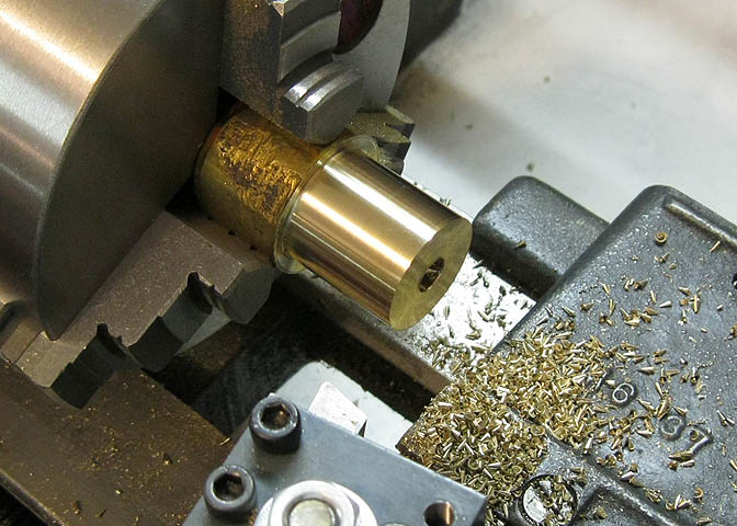
Two adjusting discs are needed for raising and lowering the filing rest. These were made of
brass, but could be steel or aluminum. These are .9" diameter, threaded for 5/16-24.
Part off the two pieces for a thickness of .15".
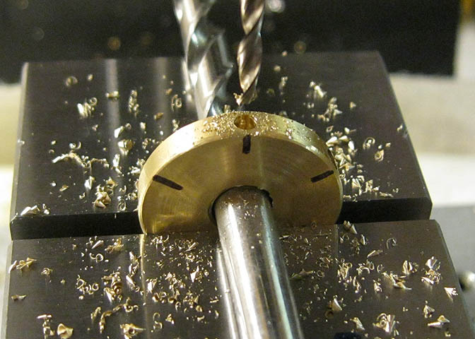
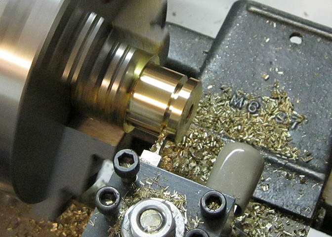
Lay out for six holes around the perimeter to be used for tightening one of the discs. Drill
the holes .2" deep and a diameter of 3/32". You only need these holes in one disc.

You should have all these pieces at this point.
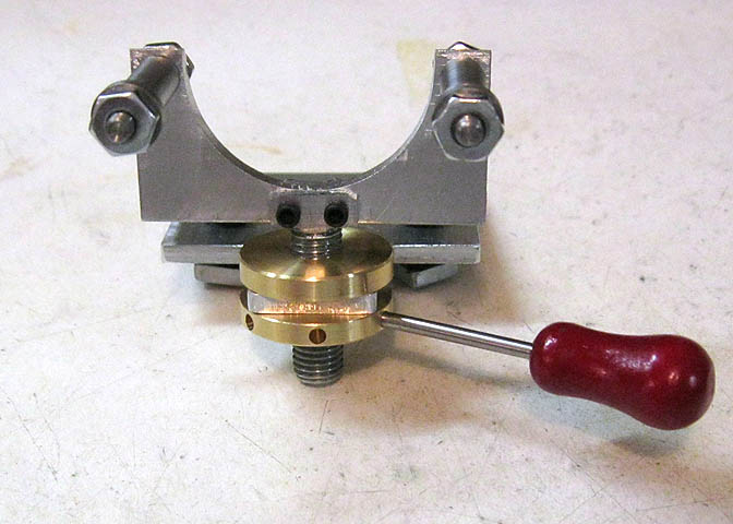
Last thing, cut a 3/32" piece of drill rod to a length of 1.6" to use for tightening the lower adjusting
disc. You may want to put a handle on it, as shown in the picture here. This red handle comes
from a Jensen steam engine. You can buy them from the Jensen steam engine company for about $1.
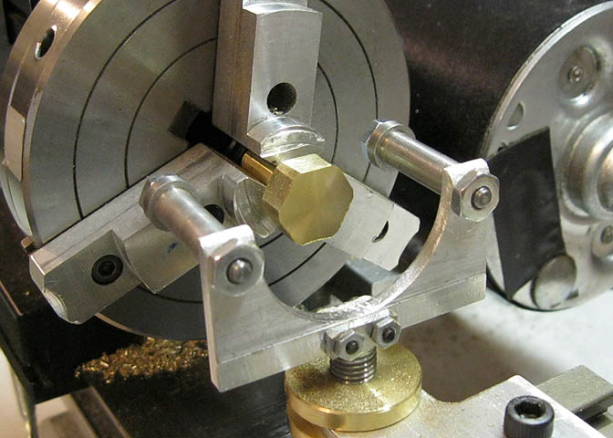
In use, the rest is mounted to the cross slide and the rollers are raised enough to start your
filing job. I've found this easiest to do in a number of steps, going around the piece three or
four times to get a nice hex. This one has just been around once, and is on its second round,
adjusting the rest down a little each rotation of the chuck until I get a nice looking hex head.
(Note, the hex on this nut isn't finished yet! Just demonstrating here.)
You need a way to index your chuck, such as the index plate shown in another article on this
web site. Headstock Indexing Plate. You can also do simple indexing using just the jaws
of your chuck.
Thanks for having a look. Hope you found this one interesting and useful!
More Taig Lathe & Mill Projects
deansphotographica.com
(home page)
Copyright 1998-2010 Dean Williams