Building a Miniature Propane Burner, Part 2
The sleeve that goes over the body (made earlier, see Part 1), needs four vent holes around its
diameter, and one larger hole through its middle that will hold the gas adjusting valve assembly.
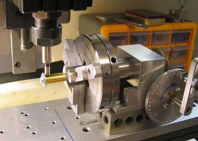
The sleeve is mounted on the aluminum arbor that was made earlier and mounted in a
chuck in my dividing head.
In the shot above, an edge finder is used to locate the end of the sleeve for positioning the first vent
hole. Then it's used to find the OD of the piece, and the mill table is cranked to put the sleeve
directly under the mill spindle centerline. Then four holes are spotted and drilled at
90 deg intervals to form the vents.
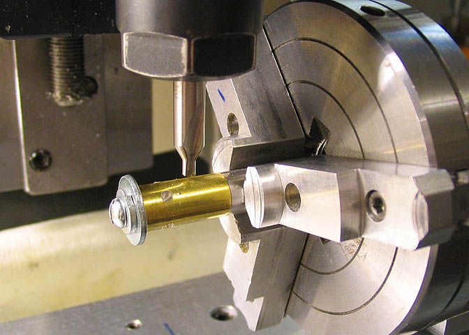
After the vents are done, the mill table is cranked over to position the piece for the larger hole that
will be for the valve. The dividing head is cranked through the required turns to put the larger hole
at 45 deg to the smaller vent holes.
The hole for the valve will be reamed later. For now, it's spotted, and a drill just under the size
of the needed reamer is used to drill through both sides of the sleeve.
A similar larger hole is drilled in the body piece, using the same size drill as for the larger hole in the sleeve.
Once that hole is done in the body piece, the final turning operation on it can be done.
Just a small bevel on the end that will face toward the top of the venturi.
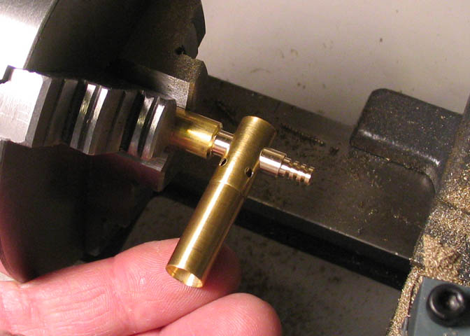
The body is now placed into the sleeve with the appropriate amount
inside the sleeve. This end will be the bottom.
You have to make sure you have the right end in the
sleeve at this point. The beveled end goes "up".
The previously drilled large hole drilled in the body and the sleeve are aligned.
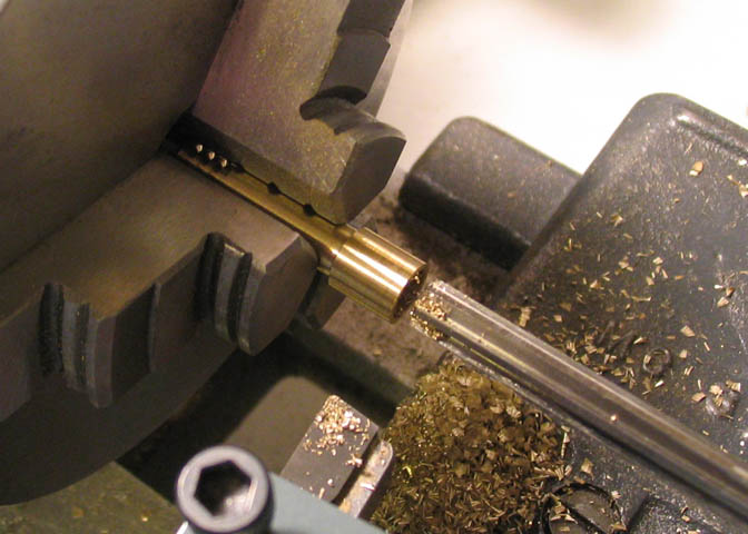
The piece is put loosely in the chuck, and the same drill used to bore the holes
through the pieces is used to align things before tightening the chuck.
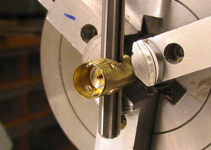
Then the reamer is run through the whole shebang to make the
properly sized and aligned bore for the valve assembly.
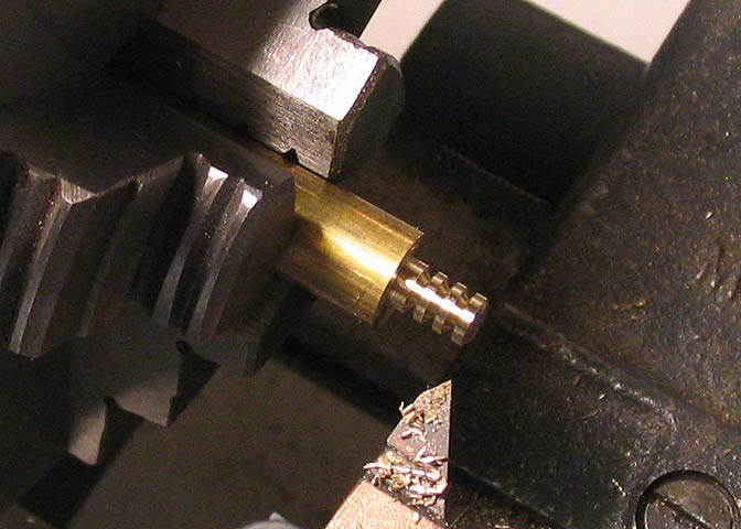
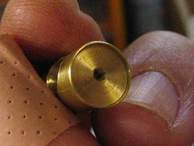
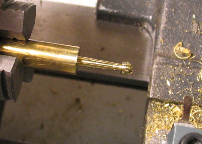
This next part shows how I made the valve. First the barb for the supply hose is turned
down to size, then the "barbs" are cut using a threading tool. I did this the way John "Bogstandard"
showed on one of the metal working forums. In the print, it has kind of a sharp edge on the end,
and he reported that it might cut through the fuel supply hose.
Then the hole that supplies the gas is drilled to the called for depth.
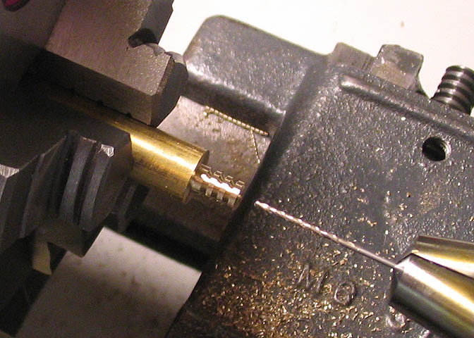
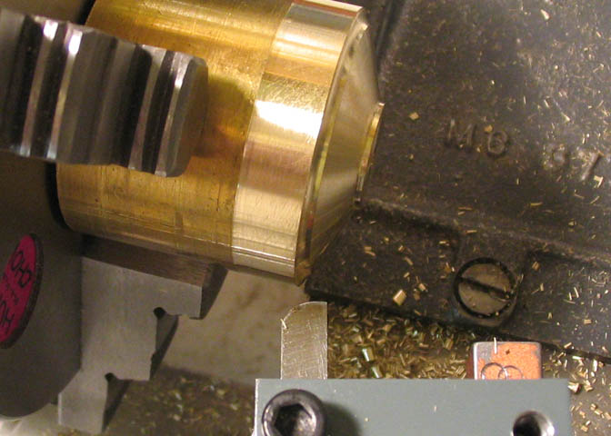
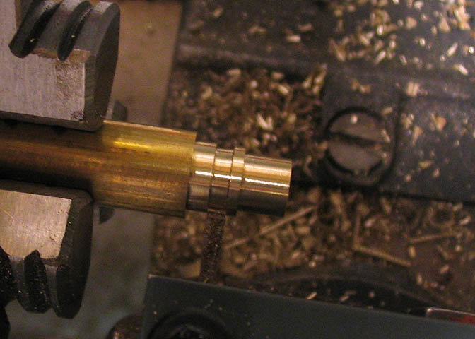
More turning to bring the center part of the valve body to size so
it will just fit into the reamed hole in the main part of the burner.
Checking for fit on the burner. This fit needs to be close!
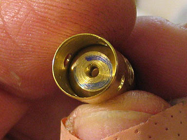
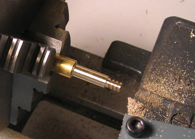
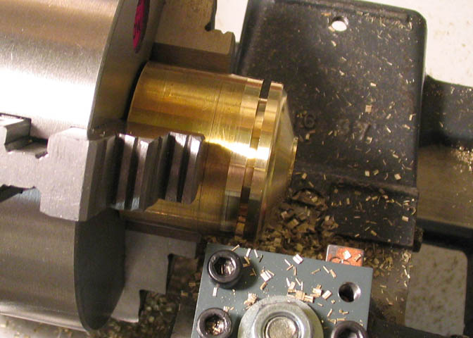
The remaining diameter, nearest the chuck is turned last, then the piece is parted to length.
With the piece turned end for end in the chuck, the end is spot drilled for the next operations.
The bore in this piece has a stepped diameter. It's first drilled for a size that will be a running fit for
the adjusting needle, then the bore for the end shown here is drilled and reamed. This last larger
diameter holds the packing sleeve and o-ring for the adjusting needle.
The last step on this piece is drilling the hole that admits propane to the jet.
Though there are a few small bits still needing to be made, I wanted to work on something
a little larger for a change. This part will be the base that holds the final assembly upright.
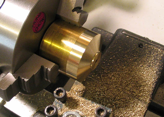
The basic shape is a disc with a mounting hole through the center. I made this similar to the
shape shown in the print, with a taper on the top surface.
Then used a tool bit ground to a radius to ease the profile on the outer top edge.
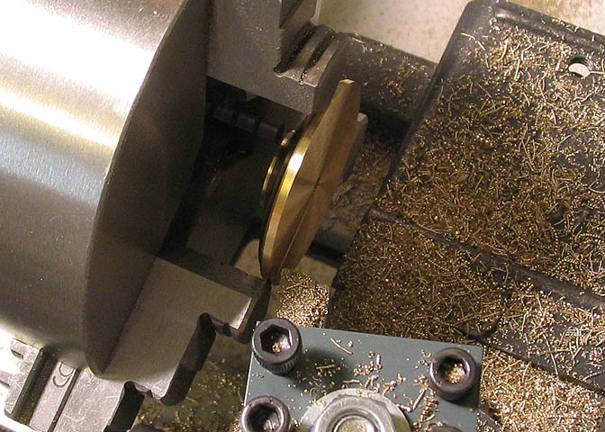
When it looked about right to me, a parting tool is run in as far as it will go, and the remaining
metal cut through with a hack saw.
Just a note, so someone doesn't get the wrong idea; The lathe was not running when I cut through
the piece with the hack saw. Actually, it was unplugged, and the saw used in the normal fashion.
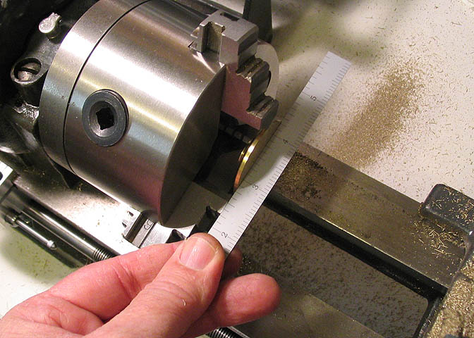
The piece is then reversed in the chuck, and the bottom side of the base trued up. A piece of tool
steel was used to space the piece out from the chuck face, the jaws tightened, and the spacer removed.
To keep the base from wanting to rock, in case the cross slide isn't cutting perfectly true, the
bottom of the base is cut with a very slight taper from outer edge to center. Just half a degree
or so will do fine. This taper effectively makes the bottom of the base slightly cone
shaped, though you can't see it.
Back to another small bit. This will be the packing piece, which will hold an O-ring in the valve body.
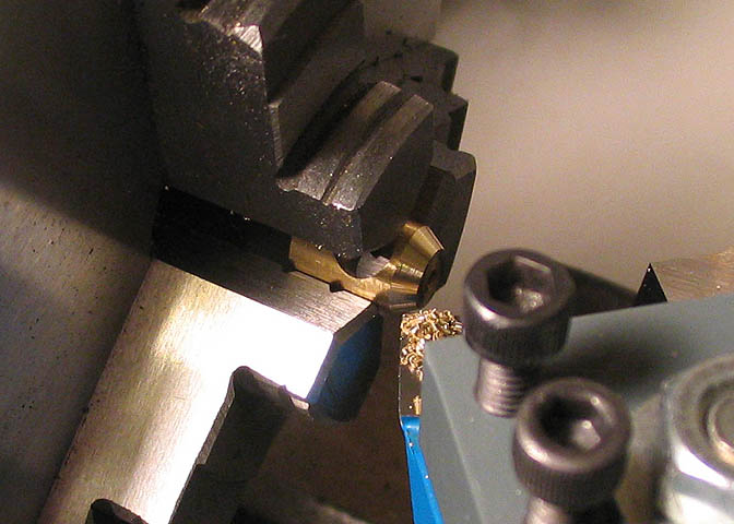
It's a basic turning job. The longer OD is turned for an easy push fit in the valve body. A hole has
been drilled and tapped through the center line of the piece, and in the shot above, it's being parted off.
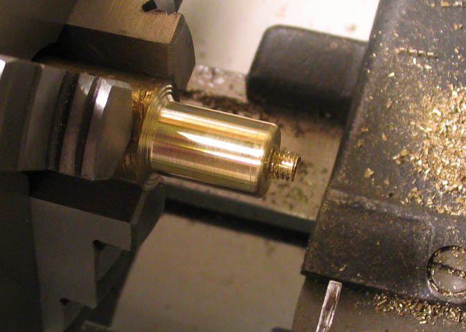
For the adjusting knob, a piece of stock is turned to the largest diameter. The small end is turned
down and threaded to fit the packing piece made in the previous step, then a hole is drilled and
reamed that will take the adjusting needle. In the shot above, I've used a file to
round one edge of the knob.
When that was done, I used a parting tool to cut a recess behind the larger diameter to allow me to
file a similar rounded edge on the other side of the knob. Then the piece is parted off.
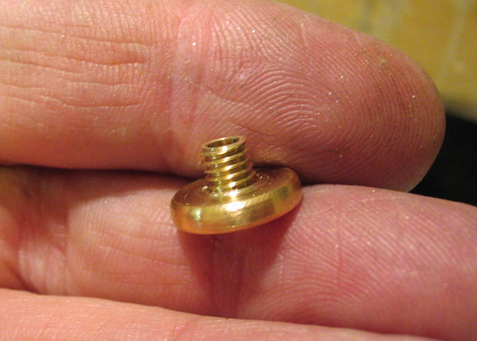
In the end, the piece looks like this. The print shows the piece being knurled,
but I think this looks nice. Don't have a knurler, anyway. It's on "the list".
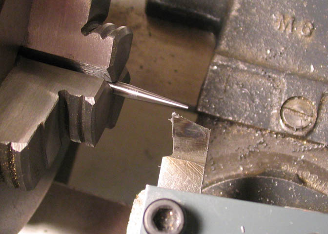
The actual needle is a simple taper turned onto a piece of drill rod.
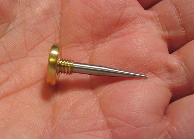
Then the needle and the knob are mated up and held together with Locktite.
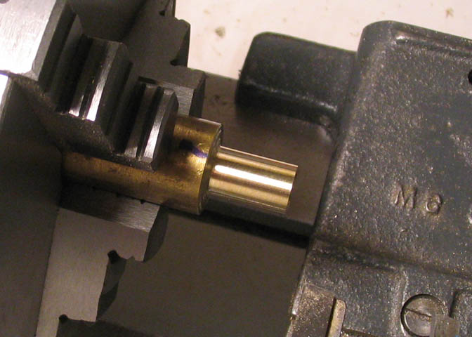
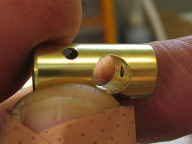
The four holes drilled in the burner body earlier are vents that let air into the venturi. To adjust
the flame, a similar looking piece is made to slip over the venturi and burner sleeve. Here the
OD has been turned, but the ID has only been roughed out.
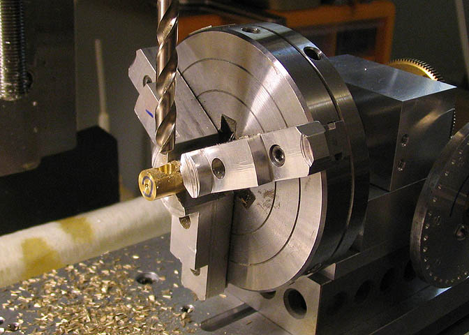
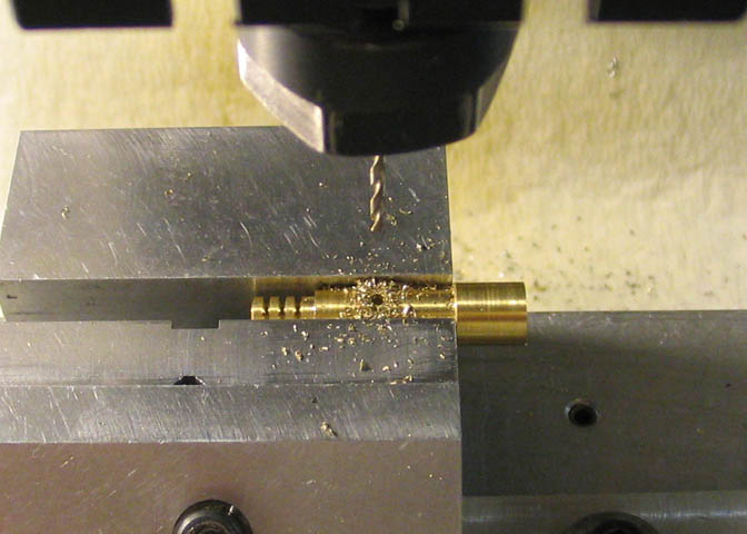
Since this piece will have holes drilled around it's circumference, I'll do that before finish boring
the ID, so as not to leave burrs inside the piece, which would make it difficult to fit over the burner.
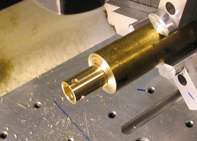
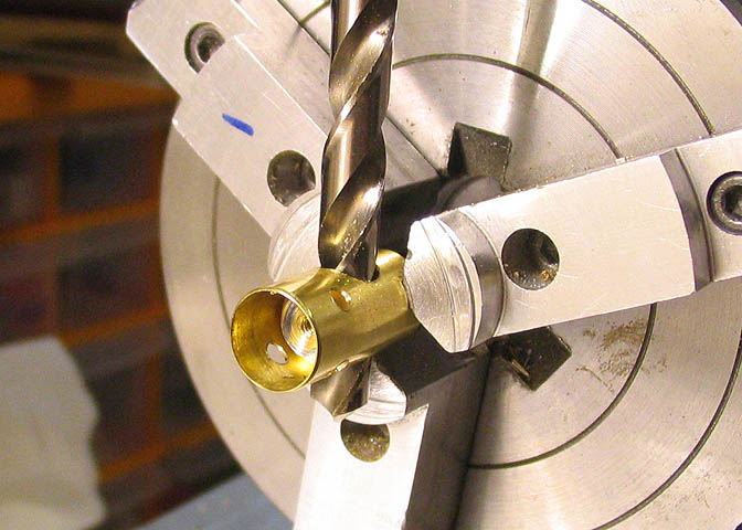
So, back to the setup on the milling machine, and four equidistant holes are drilled.
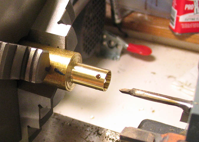
Now the finished size for the ID can be bored and it will leave a nice finish around the small holes.
It's bored to finish size, and checked for fit with the burner before parting off the piece.
The piece just made needs a small handle so it can be turned to adjust it when the burner is... burning.
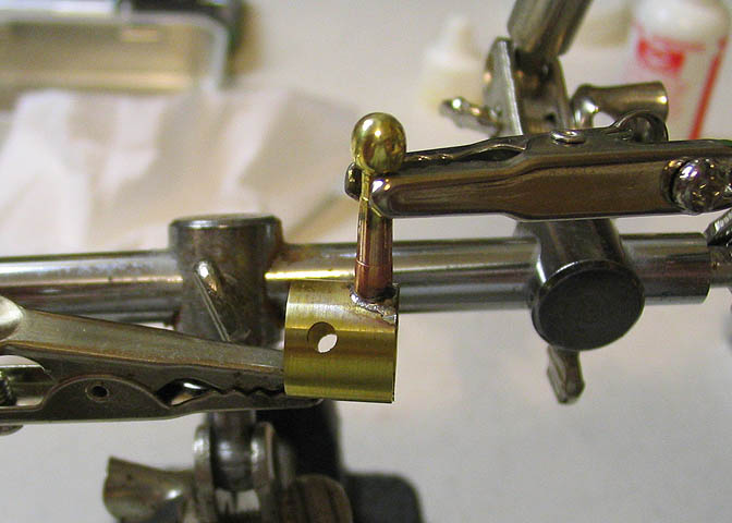
A little soldering job, and then into the pickle. After pickling, a quick rub
down with 1200 grit Clover and it will be nice and shiny, again.
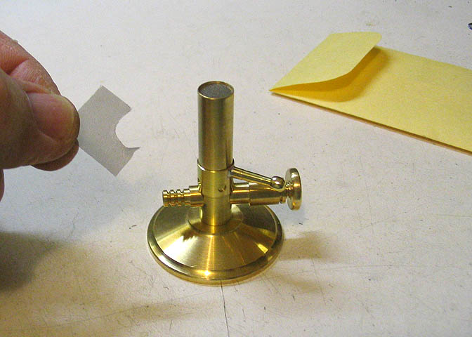
The last step is to cut the flame screen and insert it into the recess that was cut in the
venturi with the D reamer. If you order the prints for the burner, you can get this little screen, too.
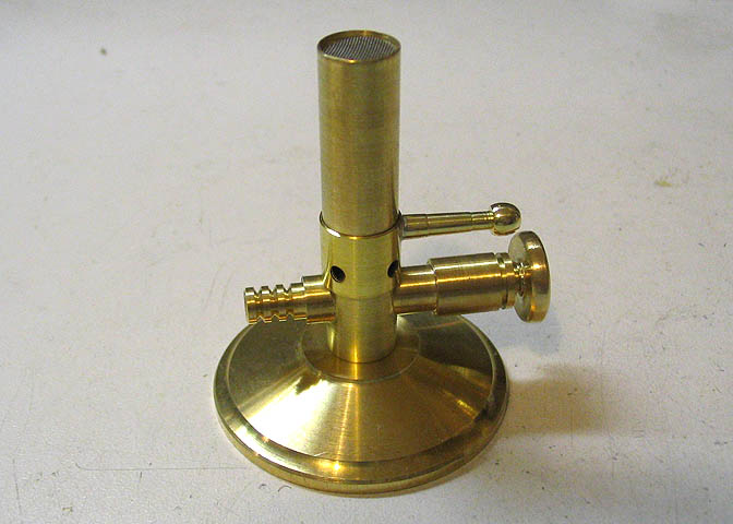
And there we go. One little burner, ready to burn something.
Here's a little video:
Thanks for looking in.
Back to Part 1
More Taig Lathe & Mill Projects
deansphotographica.com
(home page)
Copyright Dean Williams