Building a Miniature Propane Burner
This write up is a build log for the miniature propane burner sold by Jerry Howell. Sadly, he has passed on,
but his family still sell the prints for the burner at the very low price of $6.00. That's darn cheap, and if you
would like to build this burner you can order the prints from http://www.model-engine-plans.com/.
They are copyrighted material, and I respect the owner's rights. Therefore, you will not see many specific
dimensions in this article except for their use in explaining certain machining procedures.
Everything you need to know is on the prints, and I urge you to buy them from the Howell family. It's only $6.00!
The late Mr. Howell did a lot of work in, and offered a lot of support to the home machinist community. I have no
connection to his business, but feel it well worth while to purchase the prints in support of the business he had
built for his family.
So, on with the show.
I started with the jet, as it seemed the only thing that might be really difficult. The jet is
really a 2-56 brass cap screw with an impossibly small, (for me), .006" orifice hole drilled
in the end. The prints show how to make it using a slightly different method than I'll show here.
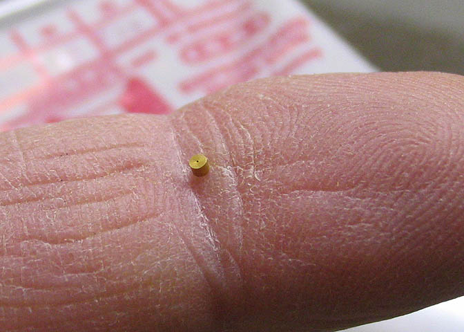
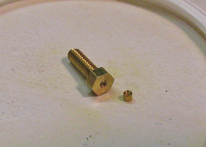
The heart of the jet is one of these little things. They are a common sized clock/watch pivot bushing,
which is made of hard brass. This size happens to have a .006" hole conveniently drilled through its
center. The O.D. is approximately .0475", which is also pretty convenient, since it is close enough to
a standard numbered drill size to make good use of it.
The prints for this jet show a watch jewel being used, but they are not as easy to find, and being a gem,
may not take to press fitting as readily as this brass bushing.
These things are cheap, at about $9.00 for a pack of 20, and can be had through most any real
horological supply. In the USA, one of those suppliers is Timesavers, (www.timesavers.com). The
part is KWM brand, #L56 bushing.
Don't let the small size scare you off. It's not that hard to work with.
First step for making the jet is to turn and face an arbor. The size of the screw that will become the jet is 2-56,
and you need a way to hold it. Spot the face of the arbor, then drill and tap for the 2-56 screw.
Once the arbor is tapped, thread in the screw and snug it up. Not too tight, as it's pretty small.
Face off the end of the screw to make sure it's flat,
then spot the center just deep enough to start a small drill bit.
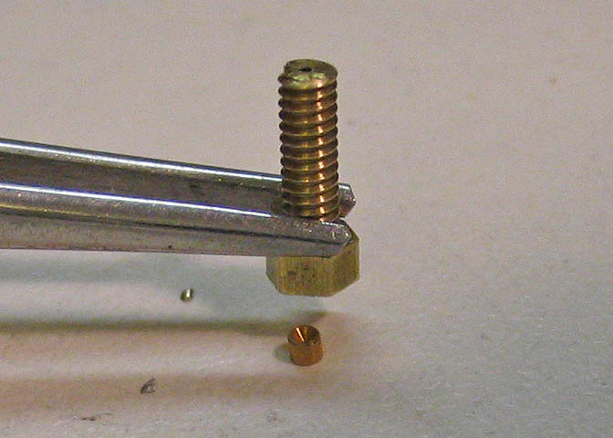
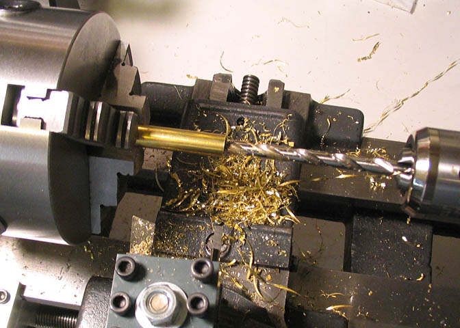
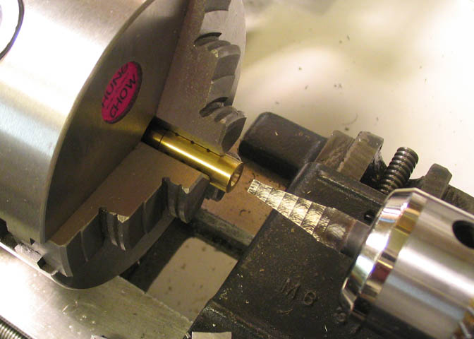
Then drill the screw end to end with a .020" bit, (that's a #76 in a small bit index). You can't hold a
bit this small with many drill chucks, so I put it in a pin vise, then set it up like in the next picture.
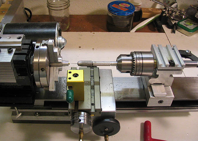
The pin vise is put into the tailstock chuck, and the chuck jaws tightened down only enough to keep
the vise from flopping around. It is not squeezing on the pin vise. The jaws of the chuck are used
as a guide, but the pin vise is free to spin in the chuck.
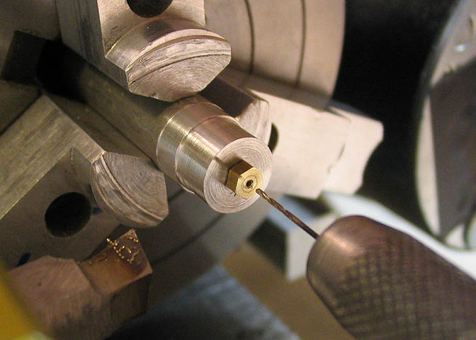
Drilling very small holes takes a light touch. Run the lathe chuck fairly fast and hold the pin vise between
the fingers, then feed it in just a dab at a time. Run the bit in just a few thousands, and back out, and in
and out and so on until the hole is completely through the length of the screw. Called peck drilling, it gives
the tiny bit the chance to shed it's chips before they have a chance to load the flutes and jam the bit,
which will often break it. Just go easy. It only takes about one minute to drill an .020" dia hole 3/8" deep.
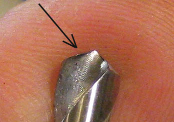
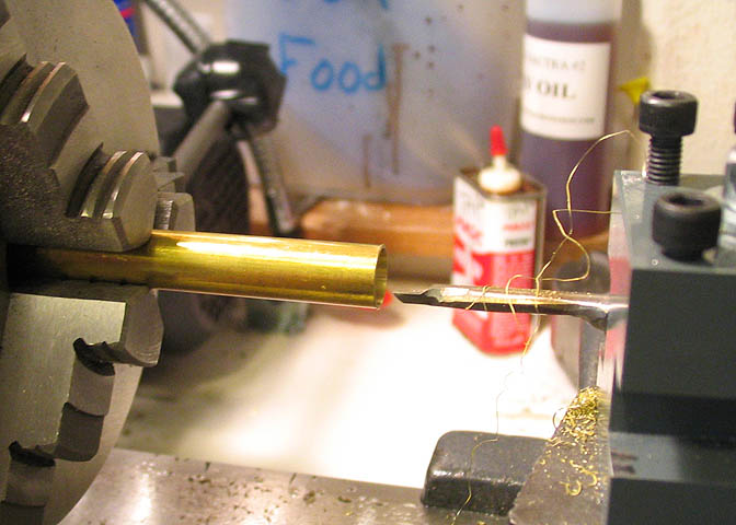
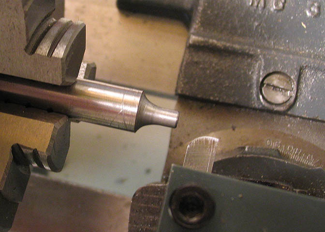
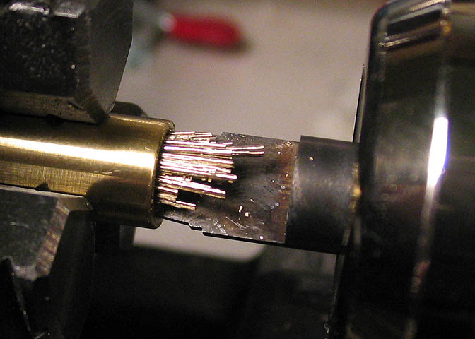
Here you can see where the bit came out the other end of the screw.
Sorry for the fuzzy picture here!
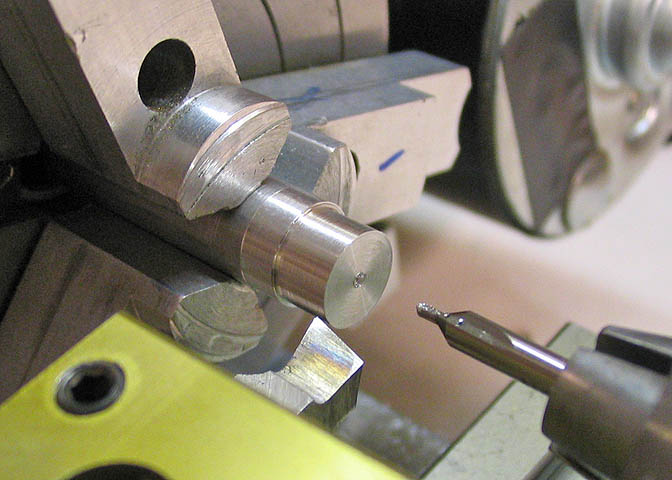
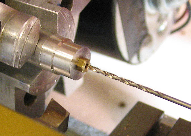
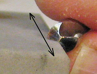
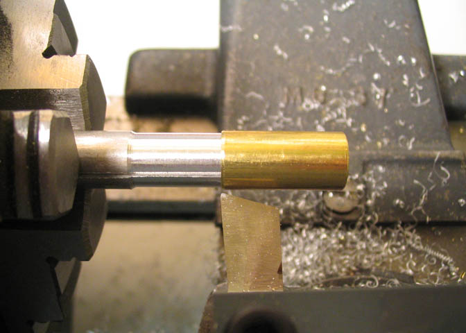
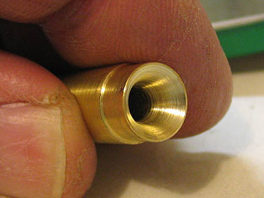
This is about the hardest part of the whole thing, and it's not really hard. A cavity has to be drilled in
the hex head end of the screw that will take the brass bushing. A #56 drill bit is just the size to make
the bushing a tight fit in the hole. The thing you have to watch for is drilling this too deep. It only
needs to go in about .040", not including the pointed end of the bit. That's a little hard to judge unless
you have superman eyes, but you can get pretty close by marking the drill bit.
You will need to hone down the cutting lips of the drill bit to keep it from being sucked into the hole
and ruining the work, (see below). Brass is a kind of grabby material, especially if you are drilling
a larger hole into a smaller one.
Once this part of the bore is done, the screw can be taken out of the arbor.
Drill Bit Honing For Brass
To take the edge off a drill to make it work well in brass without grabbing, follow these steps.
I keep an extra set of drill bits that are all honed to cut brass properly.
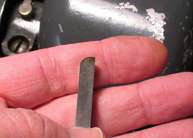
A stock drill bit looks like this. Very sharp on the cutting lips. That sharp lip works
great in steel or aluminum, but it will cause a drill bit to be sucked into brass with
quite a lot of force, sometimes breaking the bit, sometimes ruining the work.
To condition the bit so it will cut brass without grabbing the work, use a
hard arkansas stone to hone the cutting lips slightly flat.
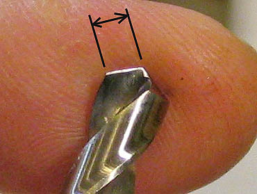
When done, the cutting lips will look like the shiny part
in the picture above.
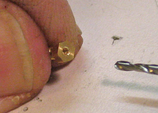
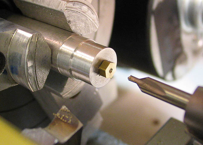
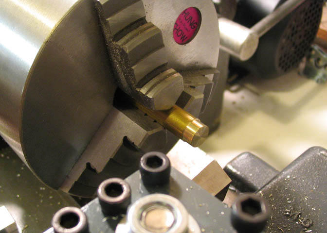
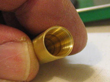
To help guide the bushing into the hole, the outer edge needs to be beveled off a little. The bit used
to drill the larger hole is supposed to make a .046" bore, but probably makes it just a little larger.
The bushing diameter is .0475", which will make it a nice snug press in the screw head, but if you
try to knock it in against the sharp corner of the hole, you probably won't get it done. To break the
edge of the hole, a 1/16" drill bit is used and turned a few rotations while holding it in the pin vise.
I think you can see the bevel fairly well here. It'll give the bushing a place to start.
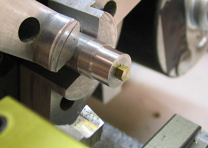
Now you just have to get the bushing in the hole, and everything will be dandy.
These bushings have one side that is flat, and one side with a bevel. The bevel in them is called an oil sink,
and when it's in a timepiece, it would hold a tiny supply of oil. You want to make sure the oil sink end goes
in the hole in the screw. The end that will be showing when it's done is the flat end.
Getting the bushing in the hole isn't as hard as it may seem. Actually, it's not hard at all. Hold
the screw with some tweezers, put the bushing on a flat surface with the oil sink side facing up and
gently lower the screw until you feel it find it's way onto the bushing. Then about three sharp
whacks with a small, hard plastic headed hammer, and it will go home.
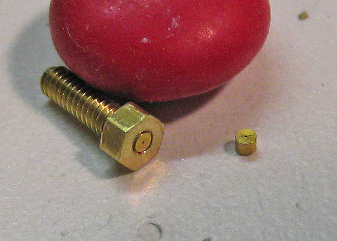
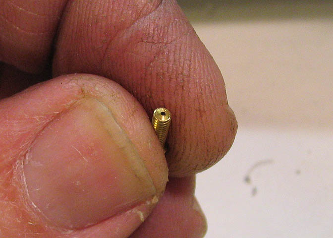
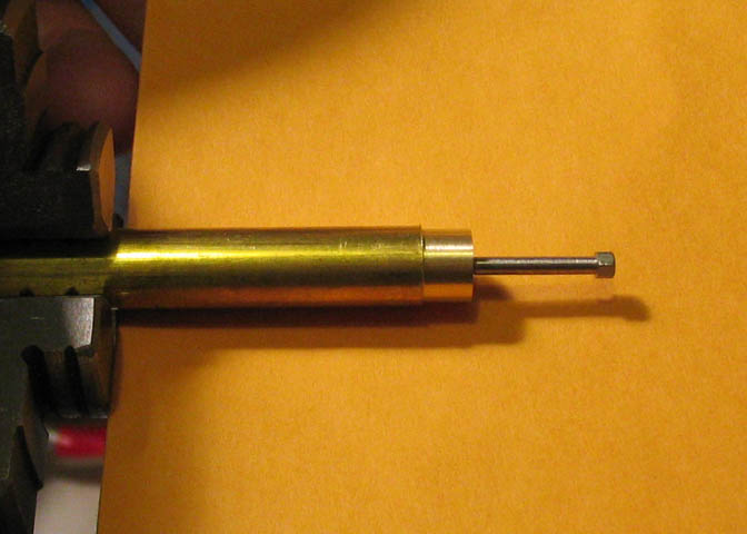
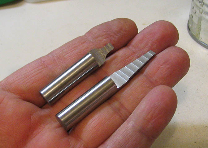
And that's it for this thing. The new jet is shown here along side another of the bushings. The giant
red thing is an M&M candy.
This might seem easy to some, and maybe somewhat difficult to others. It's not a hard job.
About 10 minutes from start to finish, including making the arbor for the screw. If you don't
have a way to drill ultra small holes and you need a jet, it might work for you.
Time to move on to the main part of the burner.
I started with the body. This part slips inside another, and I should have made it second. That
would have been a more proper order, but I started this piece not even thinking about it,
and being a knot head, just kept at it.
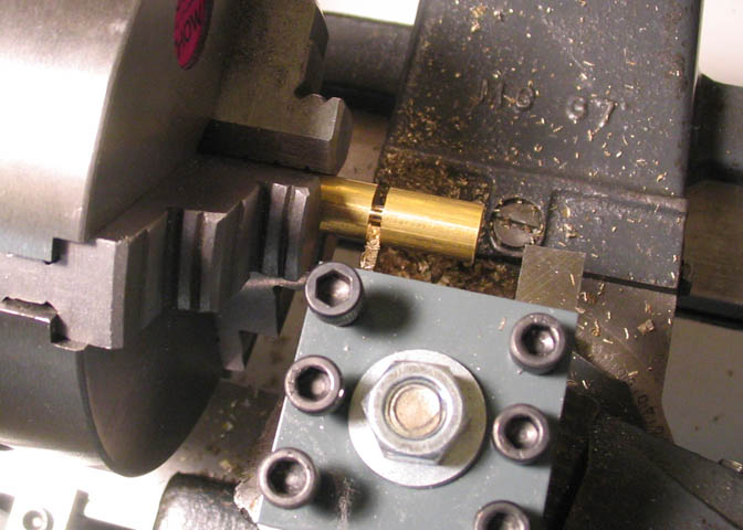
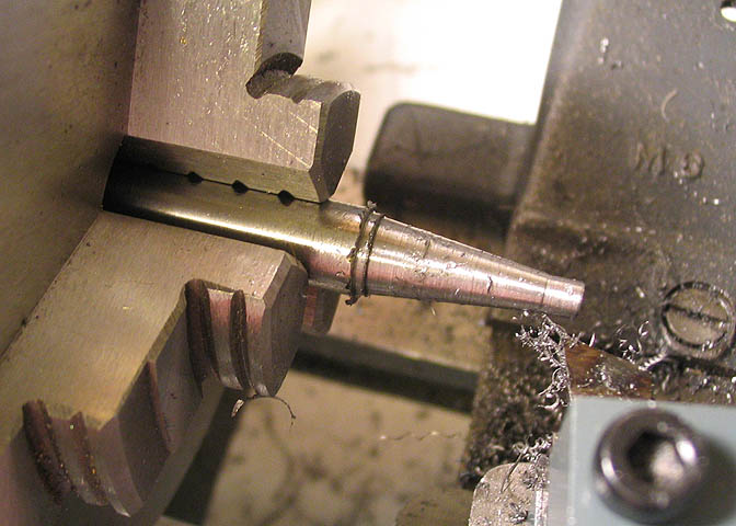
The body is just a piece of round stock turned down, drilled and tapped for 2-56 both ends, and
parted off to length. Since the hole for the valve will go through the side of this part, it was tapped
half way from one end, and half way from the other. When the valve bore is cut, it will take
out the ends of the tapped holes in the middle, so it doesn't matter if the threads are in
time from one end to the other.
Above, it's done for the moment and being parted off.
The sleeve that goes over the body part is basically a tube. I think there is commercially made brass
tubing made in the proper size, but I don't have any on hand, so it will be made from a piece of 3/8"
brass round stock. In the shot above, a piece of round stock is being drilled to a size
that will take a small boring bar.
This particular piece of brass is not the grade that I normally use. I buy 360 free machining brass
anytime it's available. Somehow, in a materials order, a piece of 260 got slipped in. 260 brass is
not free machining, and pretty much stinks when it comes to turning and boring. I'm determined to
use up this piece just to get rid of it, so it's being used to make this sleeve.
You can see from the long stringy chips in the picture above that it's not the kind of stuff
you normally want to work with.
Free machining brass will flow out of a drilled hole like small granules, or in small whiskers. When
it's turned, it comes off the cutting tool the same way. Small chips that break almost as soon as
they're formed. Very nice, but this ain't it.
A boring tool finishes up the hole to proper diameter. I made this a very
close running fit to the body piece that was done earlier.
I used a long 2-56 cap screw in one end of the body piece to make sure it fit properly.
Sliding it all the way into the end of the hole makes sure I have no taper that will trip me up later on.
The bore of the hole in this piece is quite close to the size of the body piece, as when I
push it into the bore, air pressure pushes it back out.
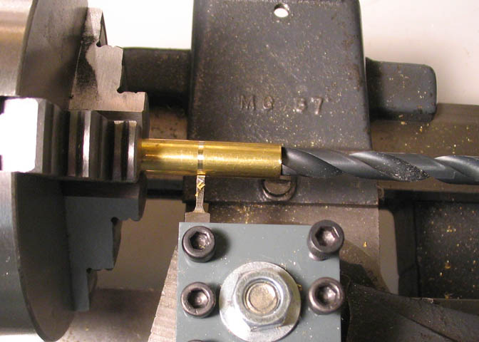
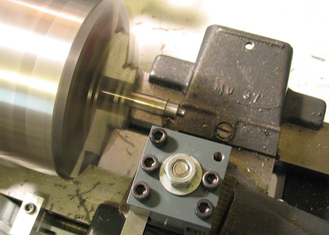
With the bore in the sleeve done, it's parted off.
The wall thickness of this piece is only about .013". In order for the parting tool to cut it off without
crushing the tube end, the bottom of the hole has to be positioned pretty close to where the parting
tool will cut. The drill bit shown in the end of the tube is to keep it from flipping around and being
ruined as the parting tool goes through.
Last turning step here is to make a mandrel that will support the
tube walls in upcoming operations. The mandrel is a disposable item.
Next part up is the venturi. This piece will have a number of operations done on it, a couple of
which are form reaming, so it's best to make sure you have 360 brass for this one.
The end of the venturi fits into the body sleeve, and that part is being turned here.
The inside of this piece has a venturi shape, like a curved bell in one end, and a tapered nozzle in
the other. They have a common bore, so after turning the end as in the above picture, the piece
was drilled through with a 5/32" drill. If you have any doubts about your drill running straight
through the piece, you might be best to drill half way from each end to minimize the error.
The majority of that hole will be cleaned up with a reamer.
To form the inside of the venturi piece, you need to make a custom cutter, (two of them, really).
To start, a HSS tool bit is ground to a radius that matches the bell shape in the short end of the venturi.
Stick with me here. You'll see what I mean in a just a bit.
The bit needs a radius of .187, or basically half the diameter of a 3/8" diameter rod. When grinding it,
if you set the tool rest on your grinder to an angle of about 7-10 degrees, it will grind the clearance for
the cutter the same time you are grinding the radius.
I used a piece of 3/8" rod to check my progress as I ground this bit. When the radius matched that
of the rod, it was good.
Then, a piece of 3/8" drill rod is chucked up, and the end of the piece is roughed out with a regular
tool bit. I left the piece of drill rod about 5-6" long, so I could work on both ends to make two
different cutting tools, and it will be easier to hold for some operations that will be done later.
The tool bit with the radiused end is used to cut the profile that represents one end of the venturi, like so.
Dial in a cut of just a few thou and advance the carriage to where you want the radius to end. Keep at
that and pretty soon you end up with a nice sort of bell shape on the end of the drill rod.
Running the lathe slow, like 50-100 rpm, and brushing on some cutting fluid
will help cut down on the chatter.
There is one more small cut to be made directly behind the end of the radius. I won't show that.
It's just a straight cut made with a regular pointed turning tool.
The piece of drill rod is now flipped in the chuck to work on the other end. This one is straight
forward taper turning, and I did it with the taper set on the compound for 7 degrees. The print
doesn't call out any angle for this, leaving you to decide for yourself. It actually appears to have
a slight curve to the taper on the drawing, but from looking at it a while, I figured it was straight.
I drew it out a little larger and between the drawing, and a couple of test cuts, came up with the
7 degrees. I doubt very much that the taper on this end is critical.
The small end is a short stretch that fits into the hole that's already been drilled through the center
of the venturi. I turned that first, then ran the carriage down to where the large end diameter
needed to be cut. Then put the taper between them.
The finish on this looks rough in the shot above. This was before a finish pass at high spindle
speed, which shined it up fairly nicely. Drill rod isn't known for it's fine turning properties.
Leave enough material for a final pass at high rpm using a tool with a slight bull nose at
the cutting tip and it cleans up pretty decent.
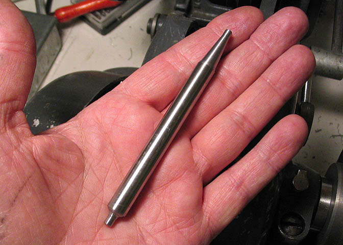
Here's a shot of the piece with the turning work done.
This is where we turn the piece into a forming reamer. This type of reamer is often called a "D bit".
I have always called it a "D reamer" because that's what the guy who taught me called them. Doesn't
really matter. One is the same as the other.
In it's simplest form, a D reamer is a piece of drill rod with slightly more than 1/2 it's diameter milled
away for a short distance on its end. I've made many of that type for regular reaming jobs on odd
sized round holes. It's a very handy thing to know how to make for when you don't have a regular
fluted reamer handy for boring truly round holes.
The one being made above is for cutting the profiled shapes inside the venturi for the burner. To
make one for a round hole, the same steps are used as for this one. You would just turn down a
piece of drill rod to the diameter you need, instead of the profiled shape I'm using here.
Look at the picture above, and you will see why I made this one on a longer piece of drill rod. It will
end up as two separate reamers in a few minutes, but for now, having it somewhat longer than finished
length aids in keeping it straight in the vise, and allows the full width of the vise jaws to clamp
against it while milling the ends.
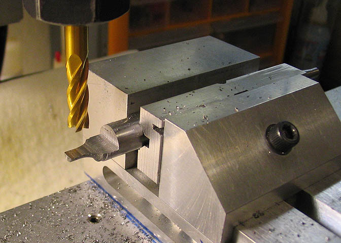
To make the end that will do the actual reaming, mill away 1/2 the diameter, less about .001". This
particular piece of drill rod is .375" diameter. One half of that is .1875". Just to make it easy I round
that figure to .188". Add .001" to that figure and it comes to .189". That's the dimension I want for
the thickness of the piece when I'm done milling.
Mill it back a little way from where the profiled part ends, and you can use the original diameter of
the drill rod to measure against with your micrometer.
After this end was done, the piece was taken out of the vise and
set up to cut the other end in the same manner.
When the milling on the piece is done, I put it in a vise and cut it in half to get my two cutters.
One for each end of the venturi.
The pieces are then hardened and after hardening, the flat face is given a few strokes on an Arkansas
stone. It's pretty important to use a real Arkansas stone, and one that is very hard. The surface of this
type of stone is very smooth. Be sure to run the cutting face, (the flat part) holding it tight against the
stone so you don't dull your edges. It takes only a few strokes, and all you really want to do is get rid
of the tiny burrs left from the milling process. The tool will already be sharp.
You only want to hone it. Not grind it. Use a smooth hard stone.
With the two D reamers done, the profiles on the inside of the venturi can be cut. In the shot
above you can see how I run these reamers. They work well in a drill chuck in the tail stock,
just like a regular fluted reamer that you can buy.
The lathe is run slow. Somewhere in the 100 rpm range, or lower if you've got it. It cuts very well
at that speed, as can be seen in the shot above. Chips build up fast, and these are from advancing
the tailstock ram just 1/16". The D reamer has to be backed out often to clear chips, since it has no flutes.
Here's a shot of the tapered end of the venturi, which will be the top of the
burner when it's done. Quite a few marks show up in the picture that are not
so easily seen with the naked eye. What I mean is, it's not as bad as it looks.
Here's a shot of the bell end of the venturi. The jet will set just below this point, and
the bell will form the low pressure area that makes these burners work.
Time to go to Part 2
More Taig Lathe & Mill Projects
deansphotographica.com
(home page)
Copyright Dean Williams