Building the PM Research Drill Press
Part 2
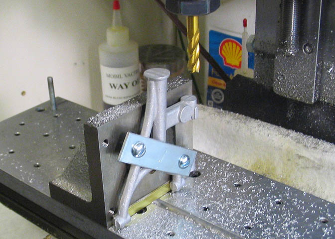
This is the main frame mounted to an angle block. The base of it is being milled flat in this pic. I took my time
getting this the way I wanted it on the angle block, since the piece has no reference surfaces. The main thing here
is to get a hole put right up the center of the thing.
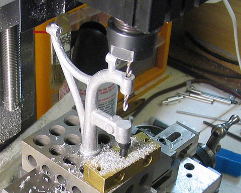
Next, the base part is drilled, tapped, and counterbored.
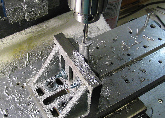
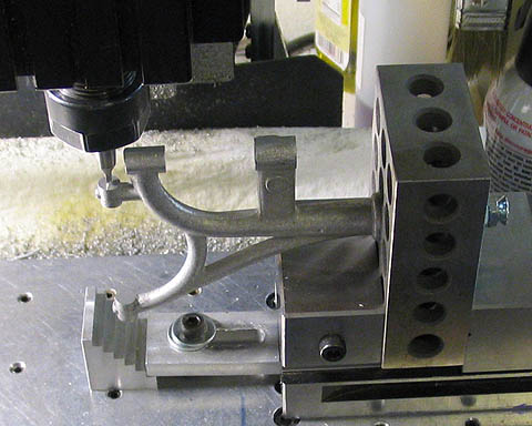
Now the bulk of the work can be done on the piece. This is the other complicated bit. Not complicated because
it had difficult cuts, but because the thing is such a strange shape. Nothing on it has a parallel side, and nothing is
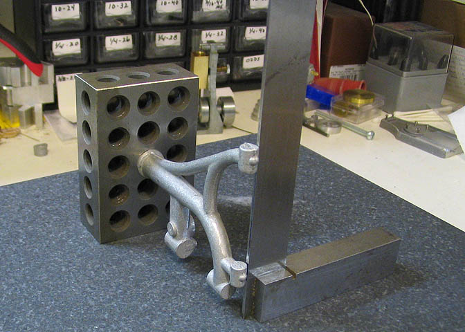
straight, so it takes some time to get setup. I mounted it to what is called a 1-2-3 block, then took about an hour
checking everything I could imagine using a surface plate, a square, and test indicator.
Once I have the piece setup, I can turn the 1-2-3 block any way I want, and know that what ever I do, the cuts will
be either parallel or perpendicular to each other. In the pic above I have it mounted in the vise and am using a
couple of jacking screws to support the arms that hang out in the breeze. This helps cut down on vibration while
making the cuts, which could cause the cutter to grab and destroy the piece.
Turn it up, cut some more.
And some more...
And some more.
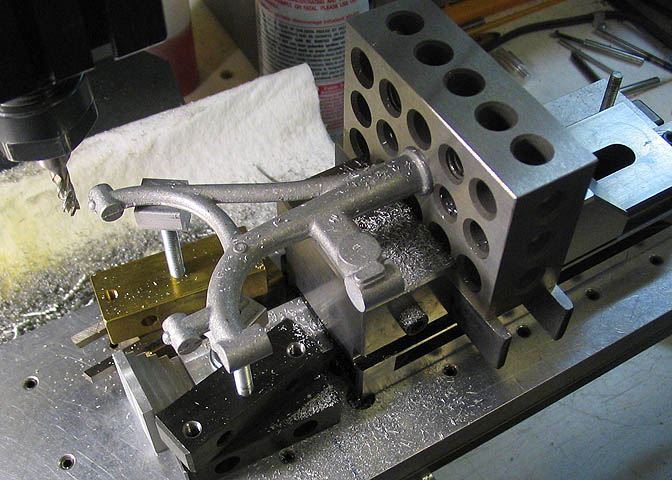
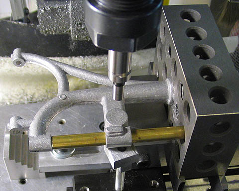
Here, a piece of brass has been run up the bore for the drill spindle so I can use that to find the center of the
bore, which lets me locate other features on the piece for further work. I spend a good many hours on this piece,
because I don't like to do things over, (although that does happen sometimes).
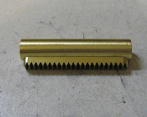
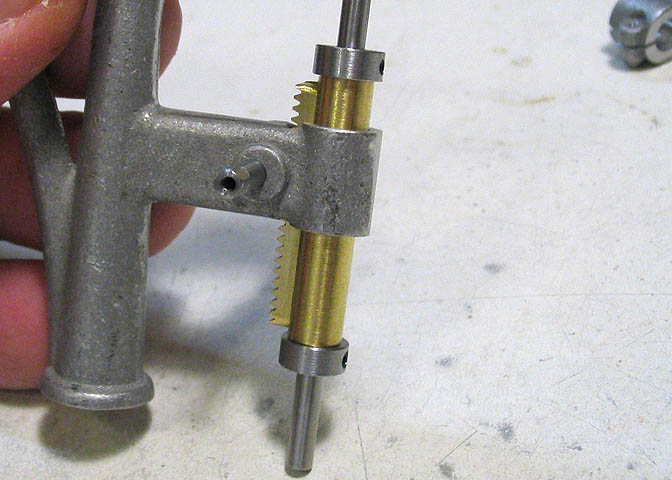
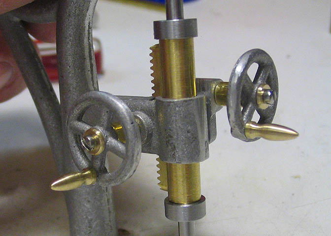
This is the spindle sleeve. Mainly a brass rod with a long slot milled in to allow fitting the rack gear. It
goes into the frame piece.
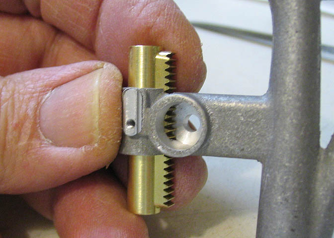
This is how the sleeve goes into the main frame casting. I spend an hour filing the slot in the frame for the rack
gear to fit, as there was not a handy way to mount the piece to use a broach. There is usually more than just one
way to get something done. Usually.
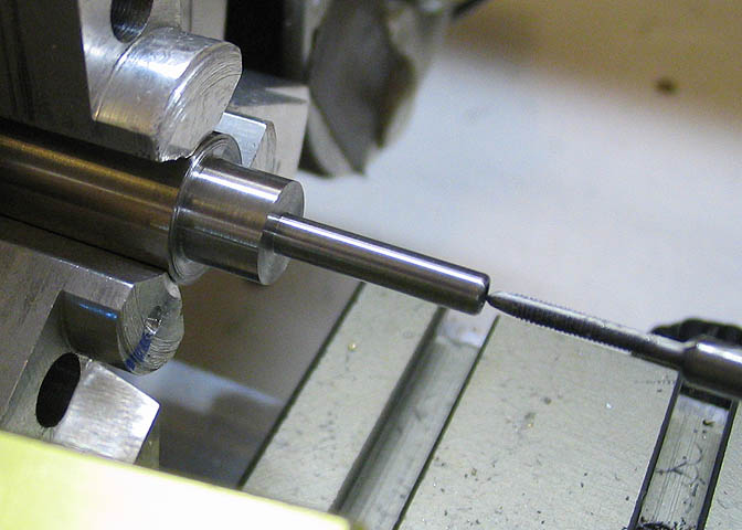
This piece will be the spindle feed shaft. It will have a handle on the end that will feed the spindle down
just like on a full sized drill press. I started this piece in a regular three jaw chuck, just to do the turning
on one end, since the starting diameter of the round stock was too large for my collets.
The piece of stock that came with the kit had a small divot in it, making it un-usable. The piece of stock I'm
using here came out of an old ink jet printer. Those printers generally have three to four good shafts in them
that are made from some of the nicest machining steel you will ever find. Those printers are also full of gears.
I find them at yard sales, usually for about $3.
After the small diameter is turned on one end of the piece, I put it in a collet in the lathe. Collets generally
hold work much more true than a self centering chuck, such as the three jaw. Using the collet will help insure
the piece runs concentric.
After all the turning work is done on the piece, and the ends are threaded, I put the filing rest on the
lathe to square the ends of the piece.
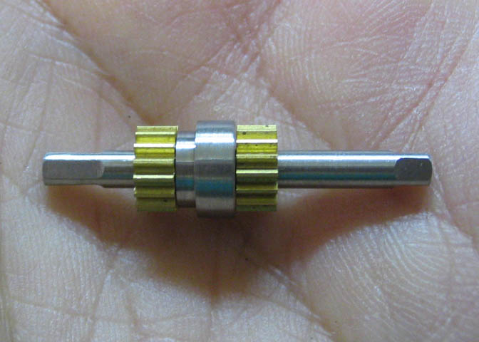
Here is the finished piece with the two pinions pushed on. One of the pinions works against the rack gear on
the spindle sleeve, and the other one runs on a worm gear that performs a fine feed function.
This piece will be the spindle. This slot runs up and down inside one of the bevel gears, and is driven by a
small screw that allows the spindle to go up and down, and still spin while rotating the drill bit.
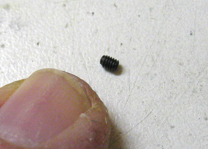
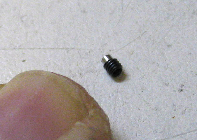
This is the set screw that will run in that slot in the spindle shaft. The prints say to cut the threads down
on one end so the screw will ride in the spindle slot. That screw is only .070" diameter and 3/32" long.
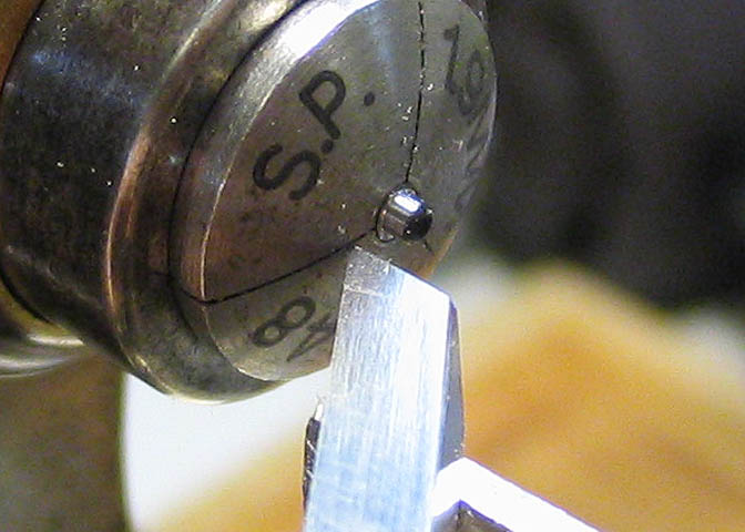
I put the screw into my little watchmakers lathe and went after it with a graver. These little screws are
hardened. A HSS graver sharpened and polished properly will cut right through hard steel. Easier than on a
regular machinist's lathe. The graver is a hand held cutter, similar to a tool for a wood lathe.
The picture makes thing look big, but in real life the graver is only 1/8" wide.
A few seconds on the watchmakers lathe and I have the drive screw done.
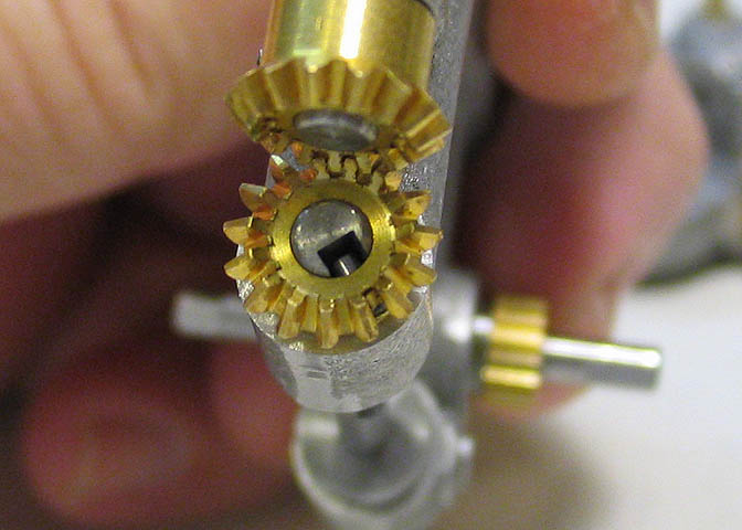
Here you can see how the screw fits through the bevel gear and into the milled slot in the spindle.
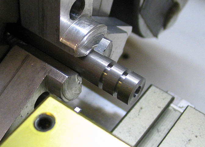
This is the start of a couple of collars that limit the travel of the spindle, (so it can't fall out). A hole
is drilled down the center of the steel rod to fit the spindle diameter, then they are cut half way through for
the next step.
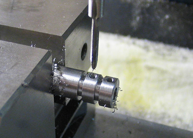
Then the holes for set screws are drilled and tapped. After this, the piece is put back into the lathe and the
pieces are parted off the rest of the way.
Here, you can see where those collars go, and how they keep the spindle held in the frame.
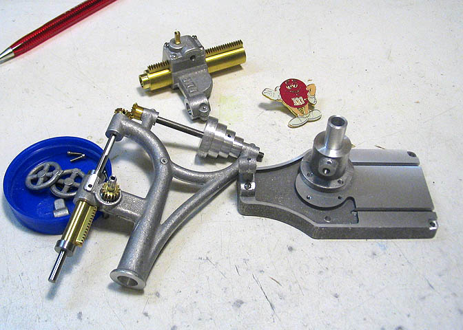
Progress shot showing the various assemblies.
This is the worm guide for the upper gear assembly. The rod going through it is to line things up so I can locate
the other holes in the proper place.
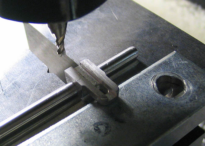
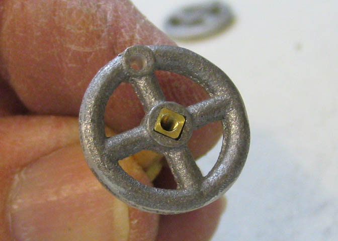
Here's some work on one of the hand wheels, making round holes into square ones.
Cutting some washers in this shot. Once I have the center hole bored, I leave the drill bit in the hole so it
will catch all the washers as they are parted off.
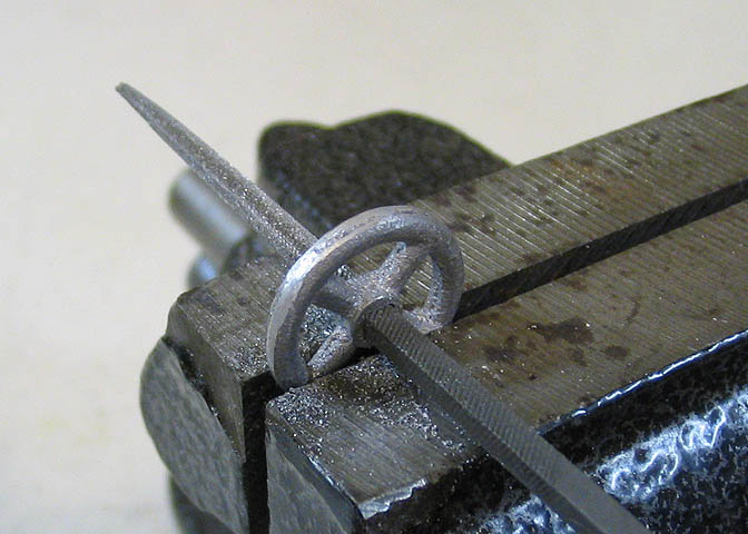
Some work on the handles for the hand wheels. For these, I use a regular lathe bit to cut away some of the excess
material, then get after it with a file.
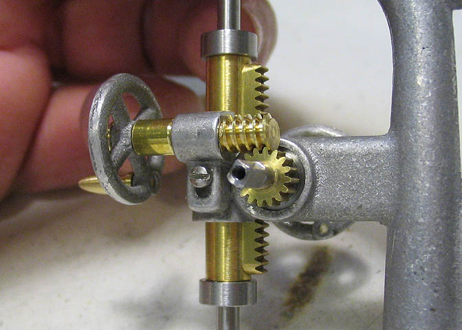
Today's progress shot showing the fine feed gearbox.
And the hand feed wheels.
This will be one of the large levers for raising the drill table, and for the other down feed on the drill spindle.
It starts as a piece of square brass rod. The handle is put on first, while the rod end is up close to the chuck.
Then the piece is pulled out of the chuck a ways and tapered from the handle on back to where the lever joins the
mounting block.
After some filing work to thin out the longer part of the lever, the square end is drilled and filed so it will
fit on a square shaft. Then the piece is annealed and bent to the shape needed.
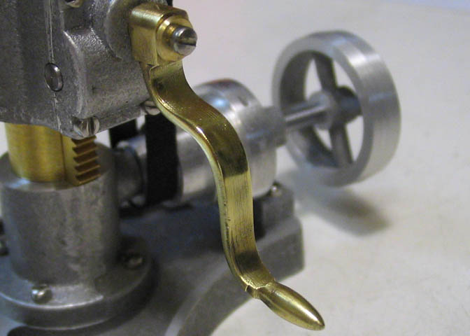
This is the lower one that raises the drill table.
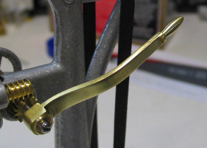
And the upper lever that provides another down feed on the spindle.
I had made the spindle that will hold the drill bits earlier in the write-up. I have been putting off this
last bit on that piece. It needs a tapered hole in the end so it can hold tapered drill bits. I set up the
lathe to cut a taper of 1/4" per foot and cut a taper on a piece of drill rod, (silver steel). This will
become a cutting tool to cut the taper inside the drill spindle.
After getting the piece to this shape, it's put in the mill and one half the diameter of it is milled away.
Then the piece is hardened and tempered.
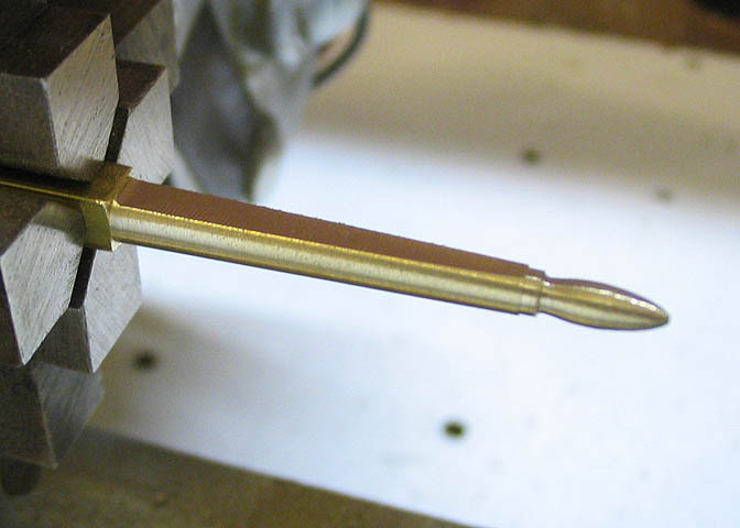
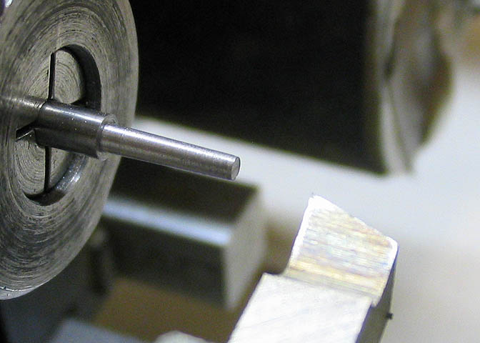
There is the cutter, ready to do its thing. It is known as a single flute cutter, or a "D" bit. This one
is quite small, and necessarily brittle, and if something bad is going to happen, it's going to happen now.
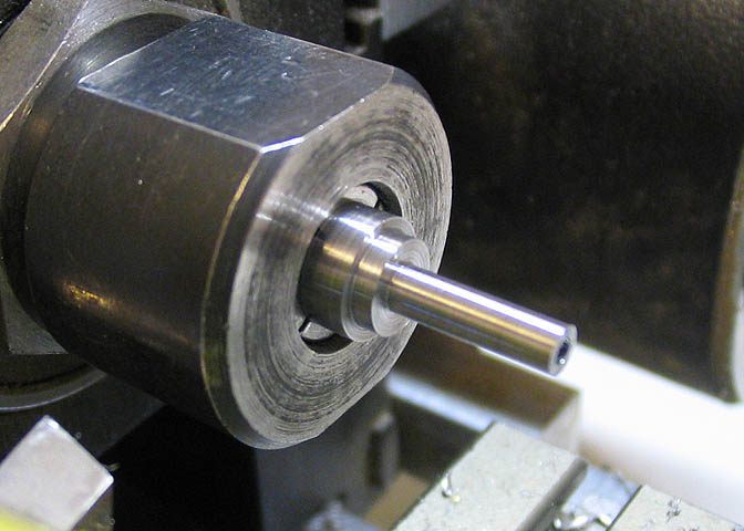
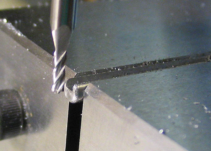
A small hole is drilled in the end of the drill spindle, the same size as the small end of the tapered cutter,
which is .070". The hole will guide the cutter as it cuts the needed internal taper in the spindle.
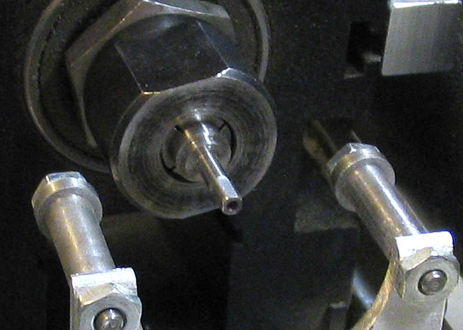
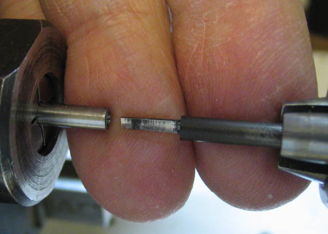
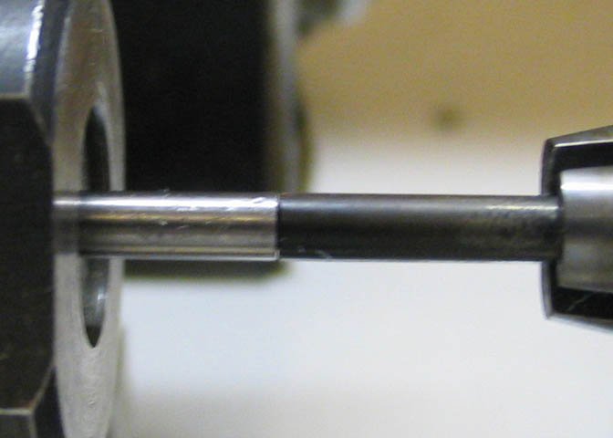
Here, you can see the chips the cutter makes as it is fed into the spindle. It peels off little curls of metal
while at the same time cutting a taper in a mirror image of itself.
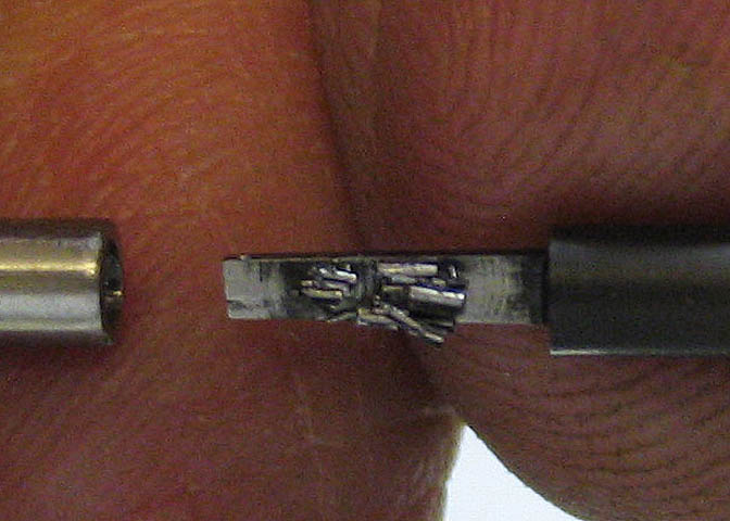
Nothing bad happened! When making tiny cutters that will cut in tough steel, there is a very good chance that
it will snap off when you start the cut. If it had broken off, I would have had to start over on the spindle
piece. Sometimes a guy gets lucky.
The cutter is fed into the pilot hole until it won't go in any further, and the tapered hole is done.
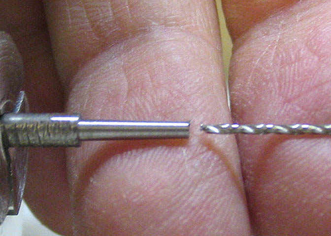
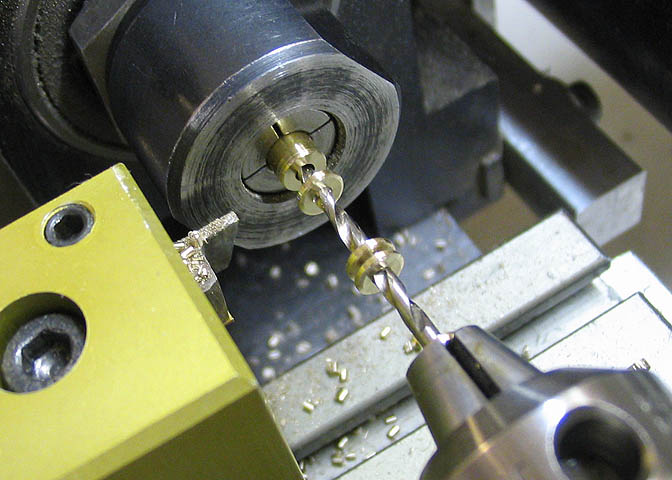
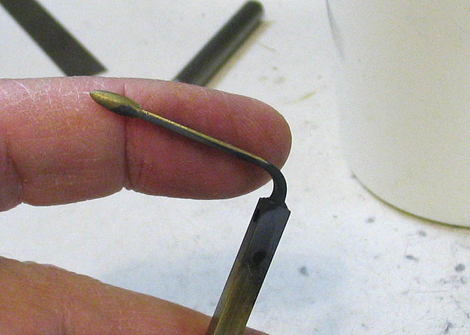
To make a drill bit to fit the spindle, I turned a taper on a small nail using the same setup that was used
to turn the taper for the cutting tool previously. Then drilled it through with the drill that will be used
in the piece.
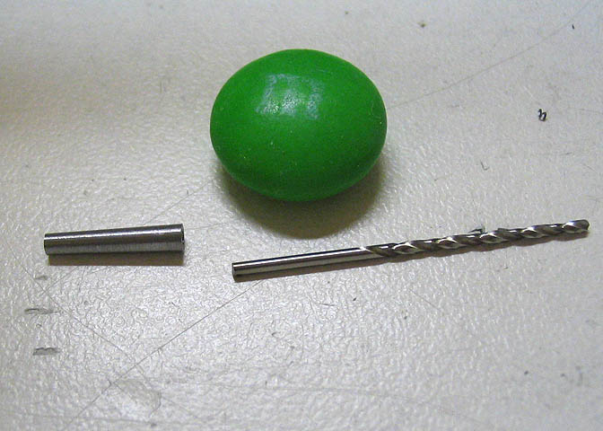
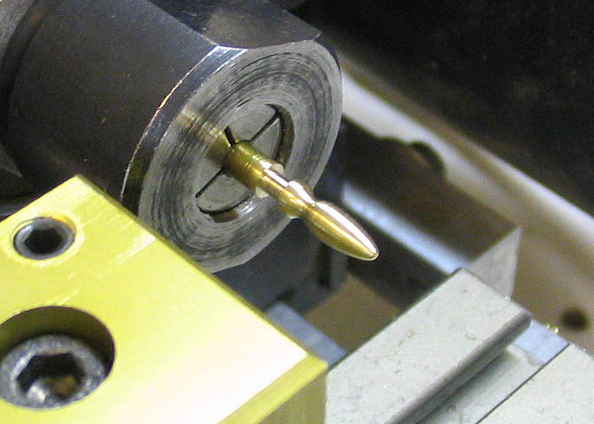
The drill bit is then held into the taper with Loctite.
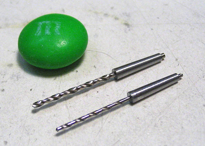
In the old days, drill bits were mostly made on a taper shank. Most drill presses didn't have Jacobs
type chucks like we have nowadays. They would have a complete set of bits that were on a taper to
match whatever taper was in the spindle on the drill press.
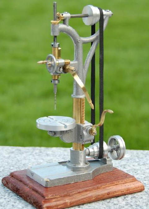
That's about it for this project. Here is a picture of the finished drill press.
This shot, and the one in the thumbnail on the main projects page were taken
by Kenneth Obionu after the drill press arrived at his home in Copenhagen.
Thanks Kenneth!
Back to Part 1
More Taig Lathe & Mill Projects
Copyright 1998-2010 Dean Williams