Building the PM Research Drill Press
Part 1
A friend from Denmark, (Kenneth) asked me if I would build one of the PM Research machine
shop casting kits for him.
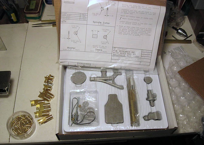
It's the PMR drill press, which is one of the many PMR machine shop accessories. I've done a number of casting kits
from PMR, and they have all been top quality. They make a lot of their products as casting kits, and some as ready
made items. I think all the accessory line machines come as raw castings. The ready made ones are in their engine
line, of which there are quite a few different models. (The pieces to the left of the box are a different project.)
Anyway, Kenneth wanted me to do the machining on this kit, and had it sent from the seller direct to my shop.
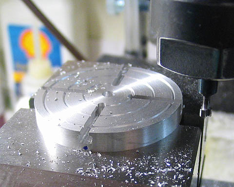
The natural place to start seemed to be the base, and then work my way up from there. First step was to file off any
casting flash and check the piece on a surface plate to make sure it was flat. Then it's mounted to a rotary table to
put in the various tapped holes.
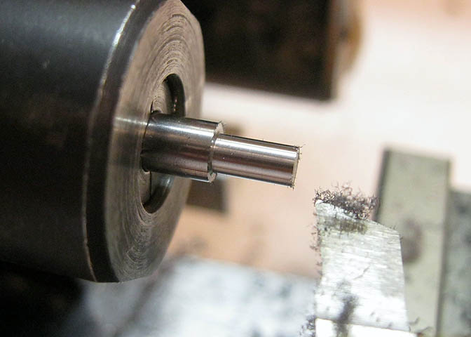
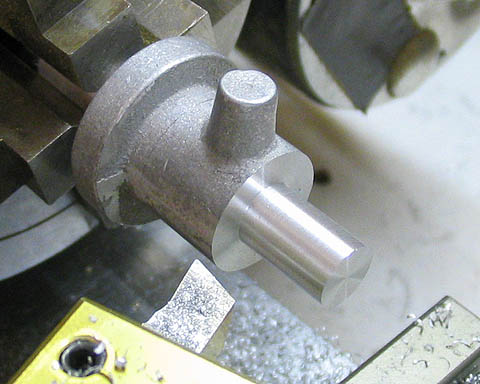
Kind of early in the game for making tools, but I need one right off. This piece will be a cutter for
putting in the T-slots in the base plate.
It's turned to the basic shape of the needed slots. Actually, it's turned to the "negative" of the slots.
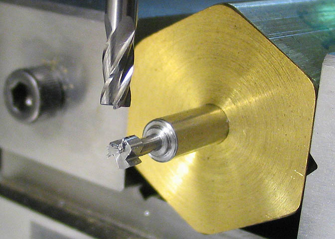
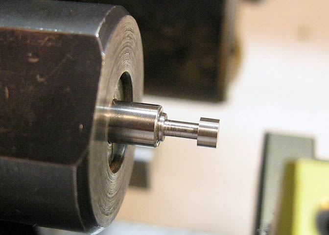
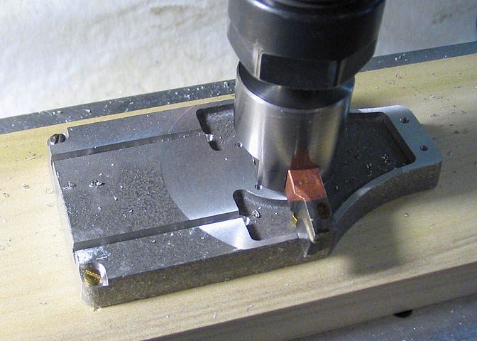
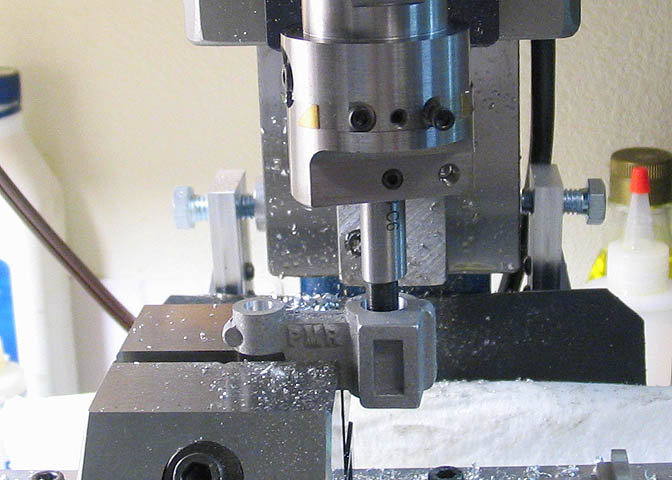
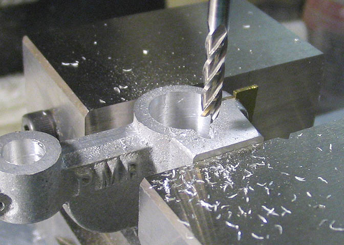
It will be a three edged cutter, so I put it in a piece of hex stock for indexing the three cutting flutes. I have
a number of these hex pieces made up just for the purpose of making cutters. In the pic above an end mill
is being used to form the basic shape of the cutting edges.
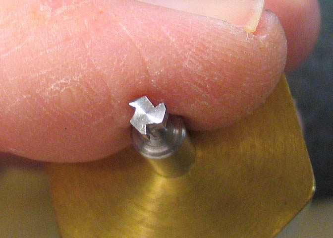
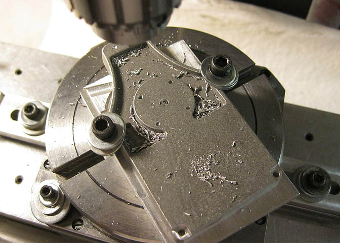
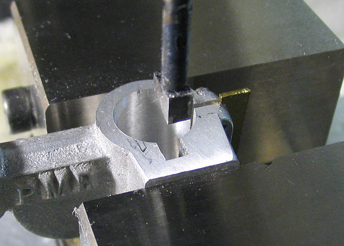
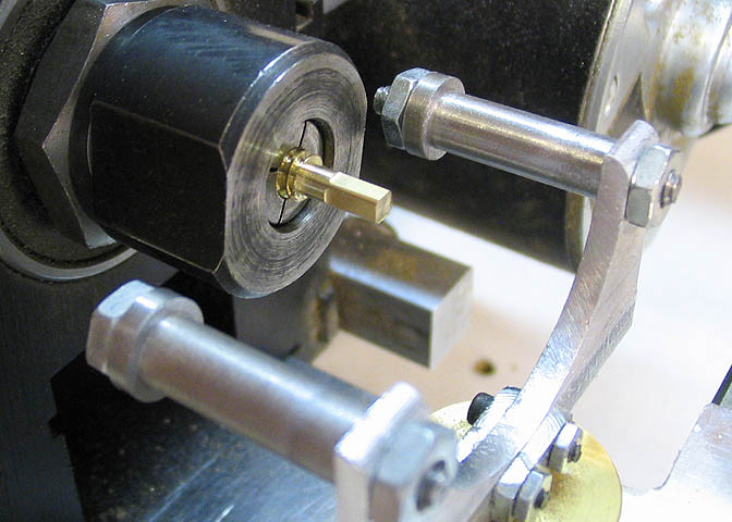
After the first round of cuts to form the teeth, the piece is rotated slightly in the hex block so I can cut the
relief on the back side and top of each tooth. Each one must have a "slope" on the surface directly behind the
sharp edge of the cutting tooth, otherwise the trailing edge of the teeth will rub and bind when they are inside
the cut. Hope that makes sense.
In the pic above, the cutter will rotate counter-clockwise. I think you can see the relief behind each tooth.
After the piece is cleaned up a little to remove the "feathers" left from the milling steps, it is hardened, then
tempered so it will be hard enough to do its cutting chores.
One thing about the PMR kits; They have absolutely great drawings. Perfect. But, they do not tell you
how to make things like cutters. If you want to know more about hardening and tempering tool steels,
have a look at the counter-bore article on the main projects page.
Now that the cutter is made, back to the project. The base has two long T-slots, which you will also find on full
sized drill presses. They are for nuts that go into the slots so you can bolt down your work.
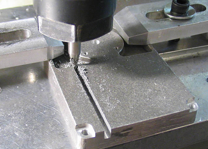
The first step here is to use a regular end mill to cut the beginning of the slot to full depth. This gives a place
for the shaft of the new cutter to go when the cutter is doing its job.
Then the new cutter is run down the piece to cut the upside-down "T" shape that makes the T-slots. These slots are
really pretty small, so this took some time. The cutter could only go in about 3/8" at a time, then it had to be
backed out to clear the slot of chips. If the chips get packed in while the cutter is rotating, it can break the cutter.
After the T-slots are done, the piece is screwed down to a piece of backing wood and clamped to the
mill table. Then a flycutter is run over the piece to give it a finish.
This piece will be the mount for the large upright piece that holds the rest of the drill
press together. Simple turning job.
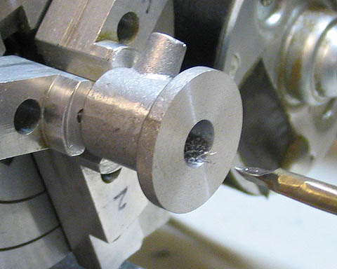
Then it's bored through for the long screw that holds the works together.

Mounted to an angle plate, it is milled and drilled.
And finally, back in the lathe so I can index the holes that will be used to mount the piece to the base.
After this piece is done, the large upright is turned from brass. No pics of that. It's just a round thing
with a hole up the center. You'll see it later.
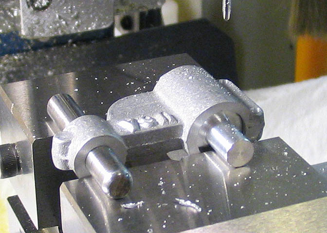
This is the gear box casting, and one of the more complicated pieces in the kit. This, and the large top
piece that will be shown later took the most time on this project due to the many setups needed to
complete the pieces. Here, the holes for the upright and the drilling table are bored.
I turned up a small jig piece to go into the larger hole in the piece. This jig piece allows me
to mount the gearbox in the vise with the two bores in the piece held in exactly the same plane.
The holes for the gearbox clamp are being drilled and tapped here.
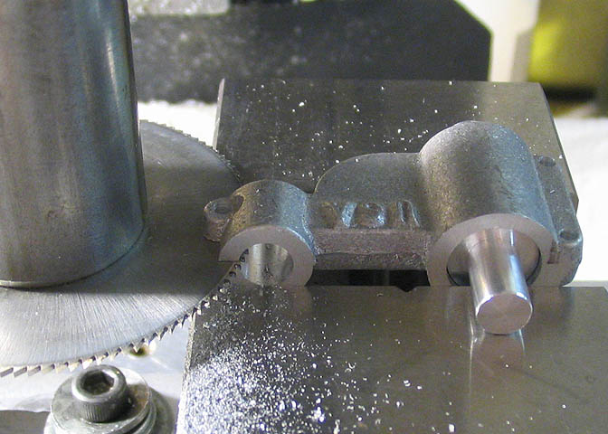
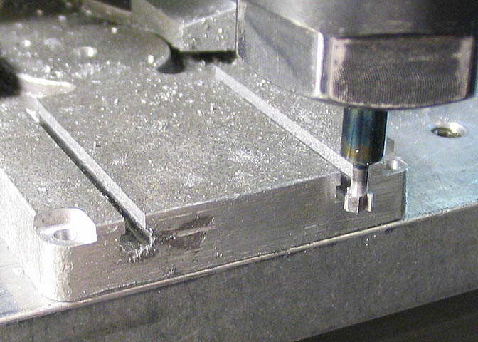
Now the clamping slot for the drilling table is cut. When you cut using a slitting saw, as shown here,
you can't run the saw through the piece full depth. It will bind and probably break. Slitting saws are
made from high speed steel, and are very hard, but also brittle. Taking a number of shallow cuts is the
way to do it. If cutting steel in this manner, cutting fluid of some sort is needed or the saw will
overheat, and again, break.
After this cut, the piece is turned over and the gearbox part of it is milled out so it can hold
the gears. No pics of that. Don't want to bore folks too much!
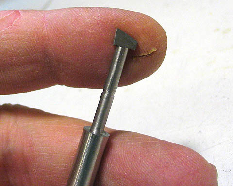
Time to make another tool. This one will be used to cut the slot that has to go
inside the bore of the gearbox. It is a single tooth cutter, and is used in the same
manner as a keyway broach. It's made from high carbon rod, (drill rod in the States,
silver steel in England). Hardened and tempered like the cutter made earlier.
To cut the slot, the majority of the material is removed using an end mill. The piece
is held in the vise, and to prevent the sides of the piece from squeezing closed, a piece of
shim brass is put between the clamping slot in the piece.
Then the broaching cutter is mounted in the mill spindle, aligned to cut the slot straight, and
the mill spindle is locked so it can't turn. The mill head stock is then run up and down in the
slot to form the square bottom, taking a few thousandths of a cut each time the tools takes a
new cut. The tool had to be run up and down about 50 times to complete this cut.
The gearbox needs a worm screw to operate. The kit came with pinion stock for the small
gears, and with a piece of rack stock for the two racks needed on this drill press. The worms
are left up to the builder.
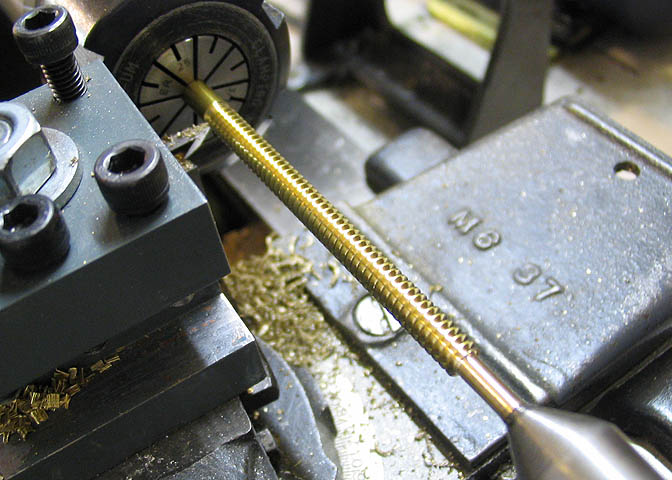
A worm is a gear with a tooth that follows a helix around a shaft. It is basically a one tooth
gear in the shape of a spiral. I ground up a cutter for the needed profile to form the tooth shape
of the worm, then set the threading gears on the little Atlas for the proper pitch, and started
cutting. I needed a couple of these worms to complete the two gear boxes on the drill press, so
just made one long one that I could cut up.
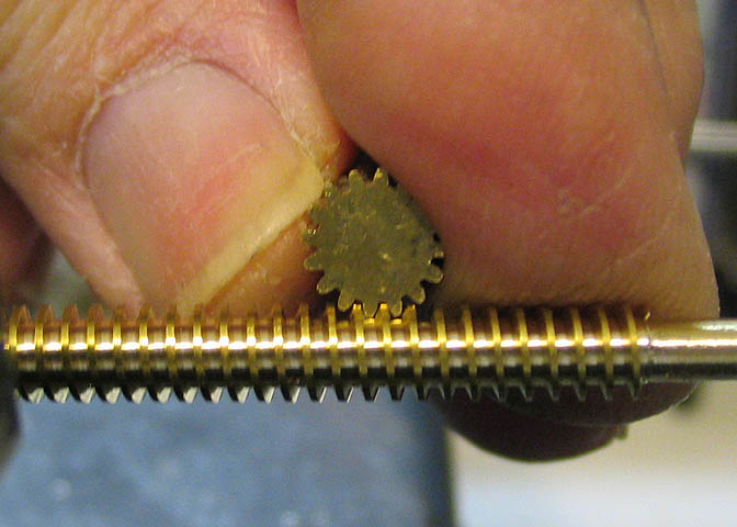
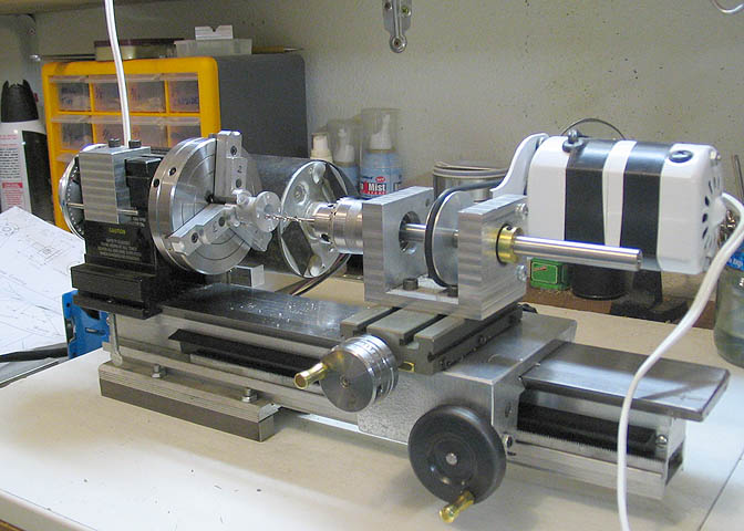
Here, I'm checking the tooth form of the newly cut worm against the pinion stock provided in the kit. It'll do.
The worm piece I made was cut into two pieces and the ends filed to square using the filing rest for the Taig lathe.
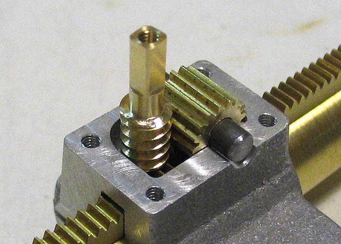
Here is the worm in place with the pinion and rack. This assembly is what makes the drill table go up and down.
The drill table is turned to shape next.
And then, more T-slots.
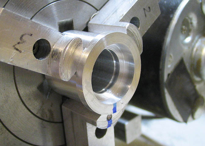
Now, I need to do some work on the cone pulleys for the drill press. These pulleys are what allow the speed for the
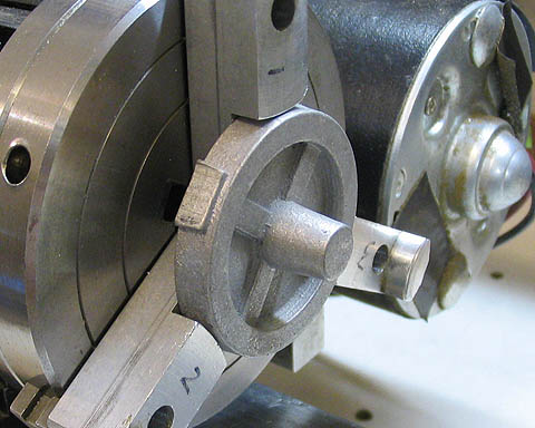
drill bit to be changed. I started by making up a thing called a "shop collet". It is basically a sleeve with a rim
that gives it a shape similar to a top hat. This kind of collet is cut to the exact needed size for the part you need
to work on, and in use it will allow you to keep a work piece well centered, even if you have to remove and replace
work piece. The "top hat rim" part makes sure the collet goes flush against the chuck jaws.
You can see a blue marker line on the shop collet and on one jaw of the chuck. This is so when I remove and replace
the collet in the lathe chuck, it will be put back in the same way it came out. This keeps things quite accurate.
A three jaw chuck is very handy, but they are not very accurate. A four jaw independent chuck is much more accurate,
but when you have multiple setups to do, it is not very fast. A shop collet will let you hold your tolerances to about
a thou, and do it pretty fast, too. Also, being fully round on the inside, it does not mark up the work piece as can
happen sometimes with chuck jaws bearing against the piece.
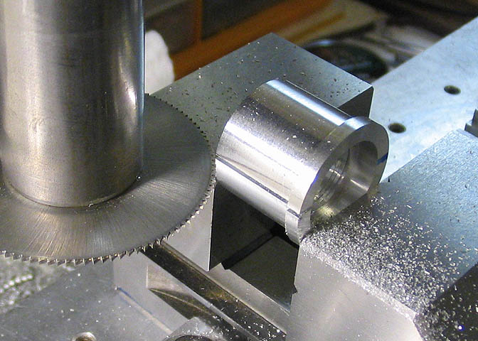
After cutting the needed dimensions for the shop collet, it is split using a slitting saw. This slit will
let the collet squeeze against the sides of the work piece and hold it tight. The slit is positioned so
it will not be directly beneath a chuck jaw when the chuck is tightened.
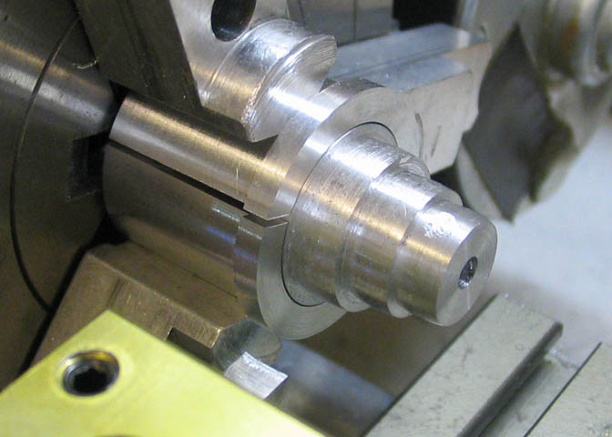
One of the pulleys is being turned here. I've ground up a form tool for the lathe to do this cutting, so I can
get the same radius on each step of the pulleys. That radius is what keeps a flat drive belt from slipping off.
On larger pulleys, the radius can be switched for two flat surfaces that come to a peak in the middle.
Go to Part 2
More Taig Lathe & Mill Projects
Copyright 1998-2010 Dean Williams