A Threading Handle for the Atlas 618 Lathe
Most imperial lathes will do an approximation of metric thread cutting using the change gears.
Using just the regular change wheels will introduce a small error to the thread pitch, but with
the right combination, you can usually get very close. Certainly close enough for short thread
runs, though on longer pieces, the error would stack up, and eventually prevent a fastener from
traveling the full length of the thread.
I need to cut some metric threads on the small Atlas, but it isn't equipped with a reversing motor,
so I have to use a different method.
If you're not familiar with the reason you would need a reversing motor to cut metric threads, here
is a short explanation;
Normally, when you
thread "inch" threads on a lathe with "inch" leadscrews, you just make
a threading
pass, disengage the half nut (back out the cross slide) and crank the carriage back to your starting point.
Then the threading dial will tell you when to re-engage the half nut to pick up the thread at the proper point
for another cut.
If you cut metric threads on an inch machine, the thread dial won't do you any good because it's geared to
the lead screw, which has a thread pitch made in fractions of an inch. The two just don't get along. If you
try to use the threading dial, the machine will just cut threads all over the place on your stock, overlapping them,
and generally making a mess. You have to leave the halfnut engaged throughout the entire cutting process.
If your lathe motor will reverse, you can just do that to get back to home base, since it will run the leadscrew
through the halfnut backwards at the same time.
Anyway, no reversing motor here, so I'll make a crank that will turn the spindle and all the related
gearing, etc., forward or backward by hand. It will work for the occasional metric threads that I cut.
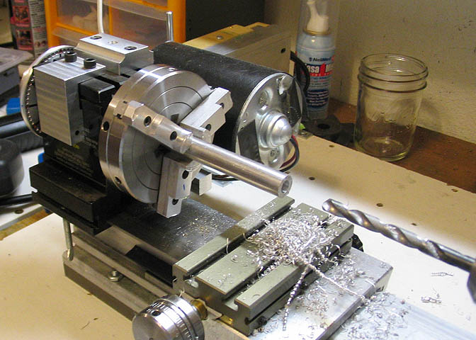
I started with a 1/2" piece of aluminum. The spindle bore on my Atlas is just over 1/2", and this
fits close enough to do what I intend to do.
First step is to drill it all the way through. I want it to pass a 1/4" threaded rod, so it's drilled
9/32". Had to go at it from both sides, so I peck drilled it to help it stay on center. It did an
acceptable job, and I couldn't see where the two holes met up.
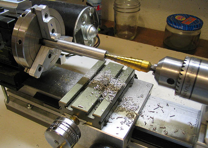
It needs a taper inside one end for an expander plug. I want the plug to be long enough
to bear on the taper for a little way. Looking through some stuff to get a picture in my
mind of how steep to make the taper, I came across this Uni-Bit. Perfect shape. It made
a nice starting point for the taper, too. I ran it in until it was just a bit shy of
the full diameter of the work piece.
It made a nice start.
To set up a boring bar to cut the ridges out of this hole, I put a regular tool bit in the compound
slide, put a straight edge along the side of the Uni-Bit, and ran the compound back and forth,
watching the tool bit tip as it ran along the straight edge. In a minute or two, I had the compound
matched to the taper on the Uni-Bit, and was ready to get to business.
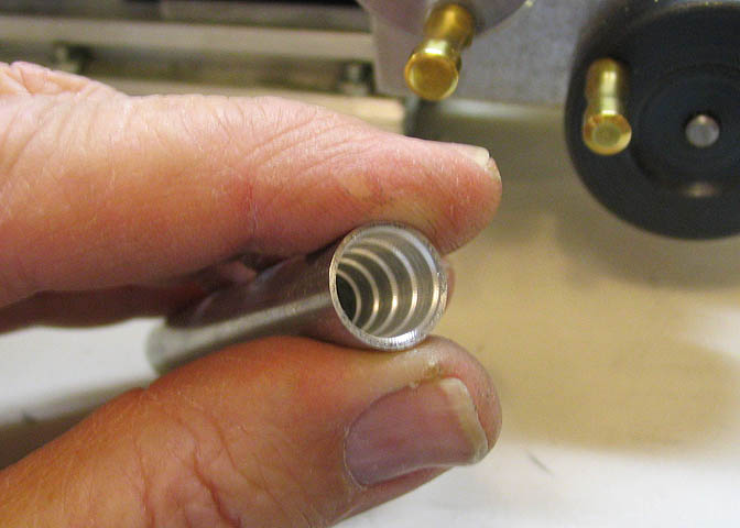
Then it was just a matter of taking out all the ridges left by the Uni-Bit, and finishing up the taper.
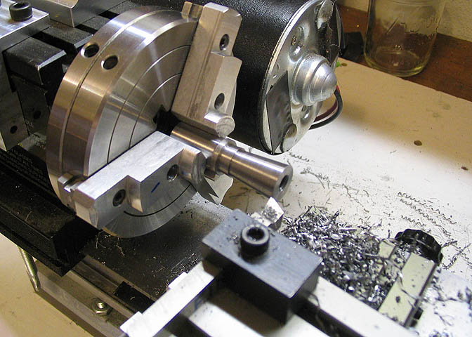
You can see that the work piece is sticking a long way out of the chuck. It's too big to go through
the headstock on the Taig lathe I'm using for this job. Usually, two to three diameters of the work
piece is about all you want sticking out of the chuck. Sometimes you can't follow the "rules".
This job could have been done on the Atlas, and then I could have been working closer to the chuck.
I have my reasons for doing it on the Taig, but it's nothing to do with the Atlas not being able to do it.
It was a preference of the day.
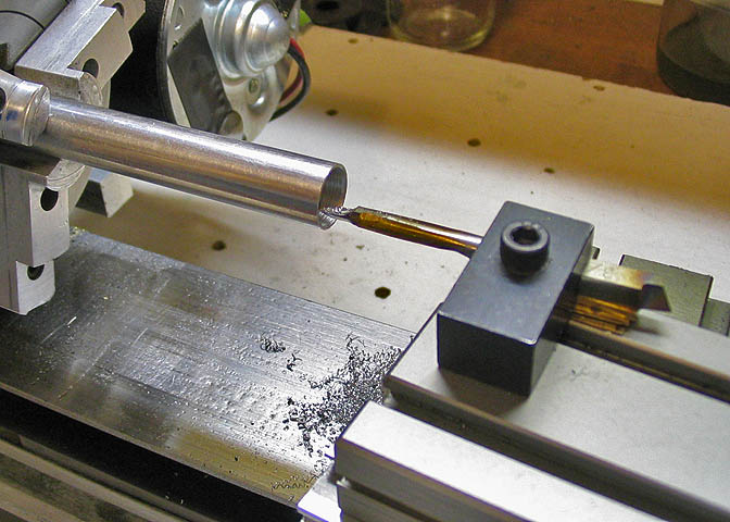
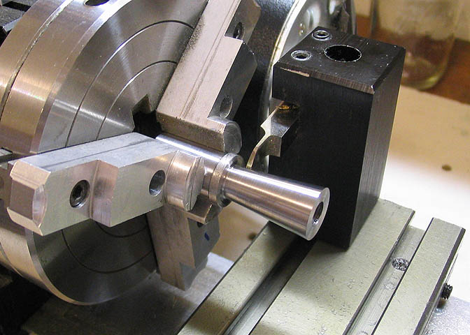
Now, without changing the compound setting, I cut a tapered plug from CRS that will go into
the taper just cut in the aluminum piece. This will assure the tapers will match.
At this point the piece has already been drilled and tapped down the center. That has to be
done before the taper plug is parted off.
When the taper plug is done, off with it's head!
If you look at the end of the plug, it appears that the tapped hole is off center. It isn't. It's
just the way the first thread of the hole sticks up that makes it look that way. It should have
been counter sunk a touch before tapping. I forgot.
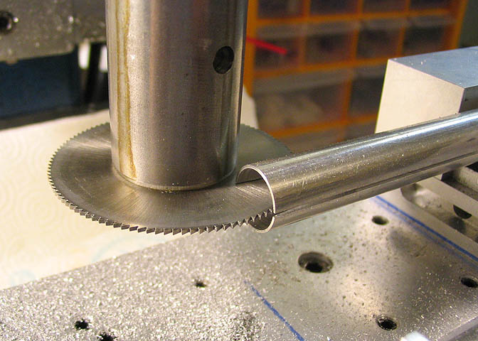
Now back to the aluminum rod that had the taper bored in it's middle. This piece will work
similar to an expanding mandrel, so it needs some slots cut. You can see what's been done here.
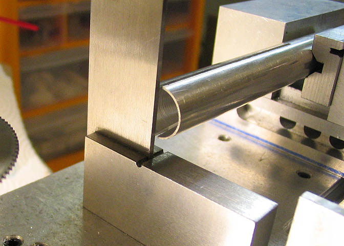
After the first two slots are done, the piece is rotated 90 deg and the exercise is repeated.
Using a square helps to get things right way up.
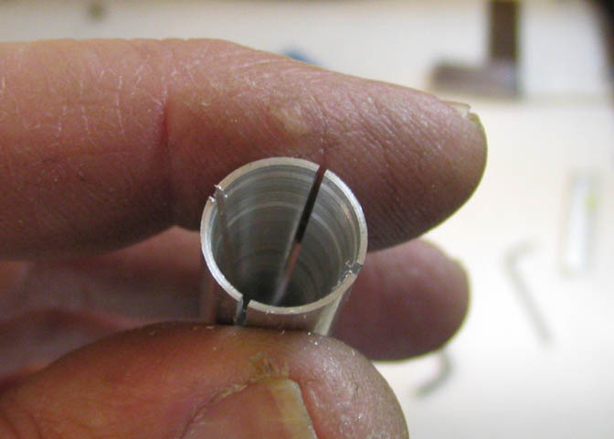
Now it's looking kind of like a collet that works inside out.
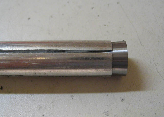
The taper plug goes in like so, and will be drawn into the rod with a threaded rod and nut.
This will expand the rod, locking it inside the spindle bore.
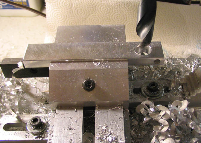
It needs some kind of offset to crank it. Just a piece of aluminum flat.
The smaller hole will be to lock it to the solid end of the expanding rod. Half of that small hole
is a clearance size for a #10 screw, the other half being tapped for same.
The bigger hole just being drilled is to fit over the rod.
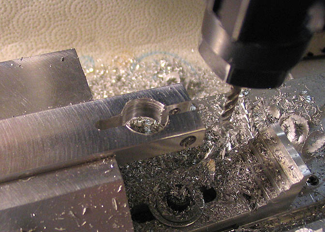
Then an 1/8" slot is milled to allow the lock screw to squeeze the piece onto the expanding
rod, (on the unslotted end). The other end of the flat bar gets a hole to mount a wooden handle.
That's just about it for the bits and pieces. I found an old file handle to use for cranking it,
but will change that out as soon as I find something I like.
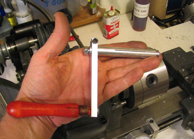
Here's the completed item.
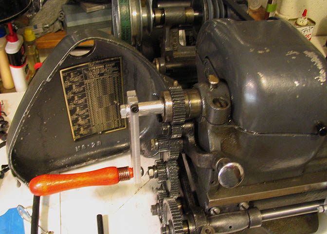
It goes into the spindle, like so. When the nut on the end of the expanding rod is tightened
down, it draws the taper plug into the rod, expanding the slotted end. It locks up very tight in
the spindle. To release it, the nut on the end is loosened, and a light tap on it pushes the taper
plug out enough to free the expanding rod in the spindle.
pass, disengage the half nut (back out the cross slide) and crank the carriage back to your starting point.
Then the threading dial will tell you when to re-engage the half nut to pick up the thread at the proper point
for another cut.
If you cut metric threads on an inch machine, the thread dial won't do you any good because it's geared to
the lead screw, which has a thread pitch made in fractions of an inch. The two just don't get along. If you
try to use the threading dial, the machine will just cut threads all over the place on your stock, overlapping them,
and generally making a mess. You have to leave the halfnut engaged throughout the entire cutting process.
If your lathe motor will reverse, you can just do that to get back to home base, since it will run the leadscrew
through the halfnut backwards at the same time.
Anyway, no reversing motor here, so I'll make a crank that will turn the spindle and all the related
gearing, etc., forward or backward by hand. It will work for the occasional metric threads that I cut.
I started with a 1/2" piece of aluminum. The spindle bore on my Atlas is just over 1/2", and this
fits close enough to do what I intend to do.
First step is to drill it all the way through. I want it to pass a 1/4" threaded rod, so it's drilled
9/32". Had to go at it from both sides, so I peck drilled it to help it stay on center. It did an
acceptable job, and I couldn't see where the two holes met up.
It needs a taper inside one end for an expander plug. I want the plug to be long enough
to bear on the taper for a little way. Looking through some stuff to get a picture in my
mind of how steep to make the taper, I came across this Uni-Bit. Perfect shape. It made
a nice starting point for the taper, too. I ran it in until it was just a bit shy of
the full diameter of the work piece.
It made a nice start.
To set up a boring bar to cut the ridges out of this hole, I put a regular tool bit in the compound
slide, put a straight edge along the side of the Uni-Bit, and ran the compound back and forth,
watching the tool bit tip as it ran along the straight edge. In a minute or two, I had the compound
matched to the taper on the Uni-Bit, and was ready to get to business.
Then it was just a matter of taking out all the ridges left by the Uni-Bit, and finishing up the taper.
You can see that the work piece is sticking a long way out of the chuck. It's too big to go through
the headstock on the Taig lathe I'm using for this job. Usually, two to three diameters of the work
piece is about all you want sticking out of the chuck. Sometimes you can't follow the "rules".
This job could have been done on the Atlas, and then I could have been working closer to the chuck.
I have my reasons for doing it on the Taig, but it's nothing to do with the Atlas not being able to do it.
It was a preference of the day.
Now, without changing the compound setting, I cut a tapered plug from CRS that will go into
the taper just cut in the aluminum piece. This will assure the tapers will match.
At this point the piece has already been drilled and tapped down the center. That has to be
done before the taper plug is parted off.
When the taper plug is done, off with it's head!
If you look at the end of the plug, it appears that the tapped hole is off center. It isn't. It's
just the way the first thread of the hole sticks up that makes it look that way. It should have
been counter sunk a touch before tapping. I forgot.
Now back to the aluminum rod that had the taper bored in it's middle. This piece will work
similar to an expanding mandrel, so it needs some slots cut. You can see what's been done here.
After the first two slots are done, the piece is rotated 90 deg and the exercise is repeated.
Using a square helps to get things right way up.
Now it's looking kind of like a collet that works inside out.
The taper plug goes in like so, and will be drawn into the rod with a threaded rod and nut.
This will expand the rod, locking it inside the spindle bore.
It needs some kind of offset to crank it. Just a piece of aluminum flat.
The smaller hole will be to lock it to the solid end of the expanding rod. Half of that small hole
is a clearance size for a #10 screw, the other half being tapped for same.
The bigger hole just being drilled is to fit over the rod.
Then an 1/8" slot is milled to allow the lock screw to squeeze the piece onto the expanding
rod, (on the unslotted end). The other end of the flat bar gets a hole to mount a wooden handle.
That's just about it for the bits and pieces. I found an old file handle to use for cranking it,
but will change that out as soon as I find something I like.
Here's the completed item.
It goes into the spindle, like so. When the nut on the end of the expanding rod is tightened
down, it draws the taper plug into the rod, expanding the slotted end. It locks up very tight in
the spindle. To release it, the nut on the end is loosened, and a light tap on it pushes the taper
plug out enough to free the expanding rod in the spindle.
It's long enough that it can be used with the gear cover closed.
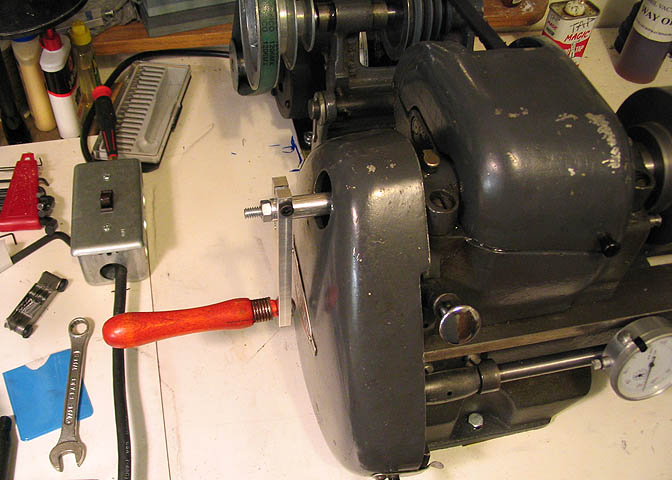
Now I can cut a metric thread to fit the spindle nose on my American milling machine!
Cranking it forward will advance the carriage as normal for cutting those metric threads.
Cranking it backward will return the carriage to it's starting point while leaving the halfnut
engaged at all times, so the the thread pitch will remain constant.
Thanks for checking it out. There's a quick video, below.
Back to the Atlas Pages
More Taig Lathe & Mill Projects
deansphotographica.com
(home page)
Copyright Dean Williams