An Indicator Mount for the Atlas 618 lathe bed
The carriage on these lathes don't have any kind of dial for keeping track of it's travel. If you
want to cut up to a corner, or have to face something to a close tolerance, you need something
to go by. I keep a few of the cheap China DI's around for projects like this.
I made something similar for my Taig a few years ago, and it worked out well.
First step was to dig through the scrap box and find a little chuck of aluminum.
It had a hole in it that wouldn't work out, but that will be taken care of soon.
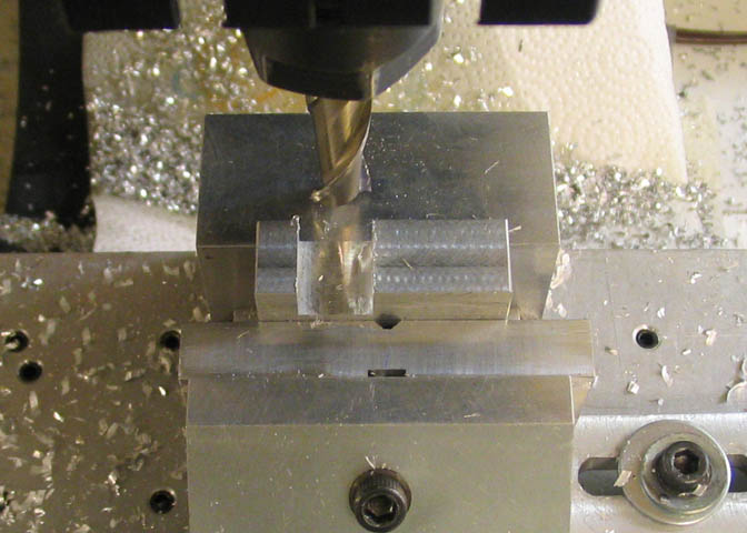
After milling the edges square, an end mill was used to cut the large slot that will
fit on the edge of the lathe ways.
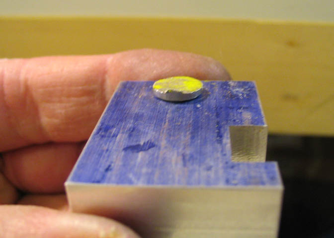
Then, to take care of that hole, I chucked up a piece of 3/8" al rod in the lathe and turned down an
end that was about .002" over sized for the stray hole. Then mashed it into the hole and cut
off the parent piece, like so.
The other side looks like this, but both sides will be flat, soon enough.
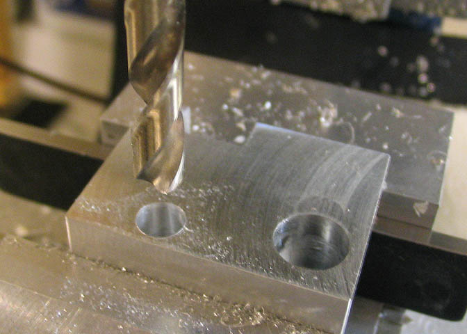
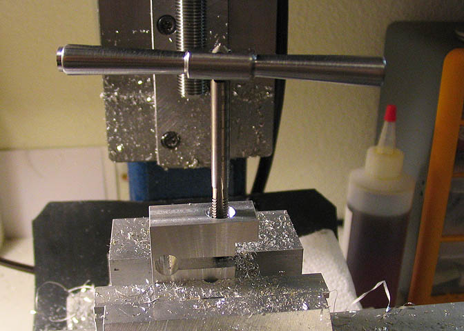
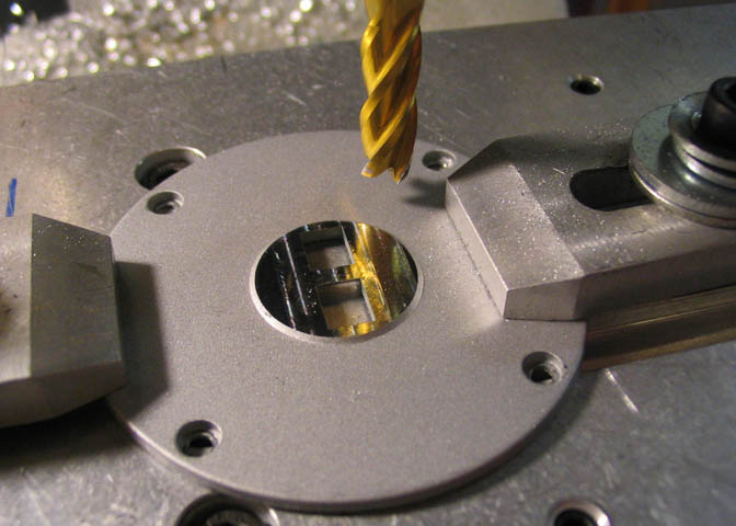
Now the piece is put into the vise in a convenient position so I can get a few operations done
in the one setup. First the end mill is run over the surface to get rid of the nub left from patching
the hole, and then a new hole is bored for the shank on the DI. I used an end mill for this hole,
since it was already in the mill spindle from running the surface on the piece. It was either center drill,
drill, and ream, or just plunge. I took the plunge.
Plunge cuts create strange forces, on any milling machine. Great big machines don't mind quite so much,
but if you are using a small machine and want to plunge cut with an end mill, lock the gibs on the X and
Y to keep from putting the machine through some strange vibrations. It's easier on your nerves, and the
machine will appreciate not having the leadscrew nuts banging on the leadscrews, too.
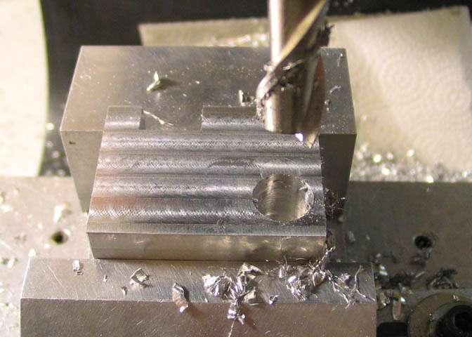
Then a 1/4" hole is drilled on the center line of the larger slot, and 1/16" from the edge farthest
from it. This will be the pinch relief hole. It will let the top of the piece flex when it's tightened
down on the lathe ways. You'll see.
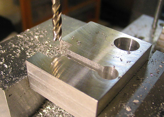
Now a pinch slot is milled from the hole to the cut out for the lathe ways. Now you can see
how it can pinch on lathe ways. The slot is cut all the way through the piece with a 1/8" end mill.
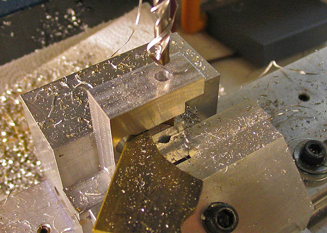
This hole will be for the cap screw that squeezes the top of the piece down on the lathe way.
The top half of the hole is clearance diameter for a #10 screw. The bottom half is drilled for a #10 tap.
Normally, this hole should have been done first, when the piece was fully intact, so the top part of
the clamp wouldn't be smashed down to the lower part of the clamp by the pressure of the drill bit.
I just used a piece of 1/8" inch scrap to keep that from happening. Doing the other steps first was for
"ease of manufacturing", and faster since I had extra milling steps due to the wayward hole in the
work piece that needed plugging.
The top is counterbored a little. It won't take a full C'bore, because the bottom of the head on
the socket head screw would hit the top of the lathe ways, so I just made it a rather deep spot face.
Shop made C'bore.
When the top side of the hole is done, the bottom half is tapped 10-32.
Shop made tap handle, too.
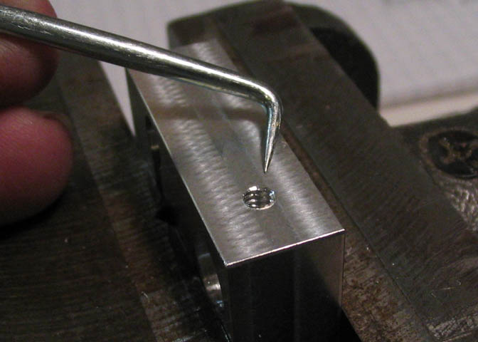
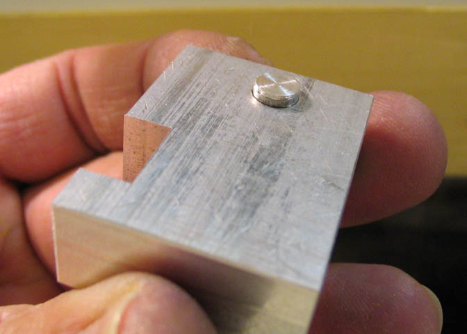
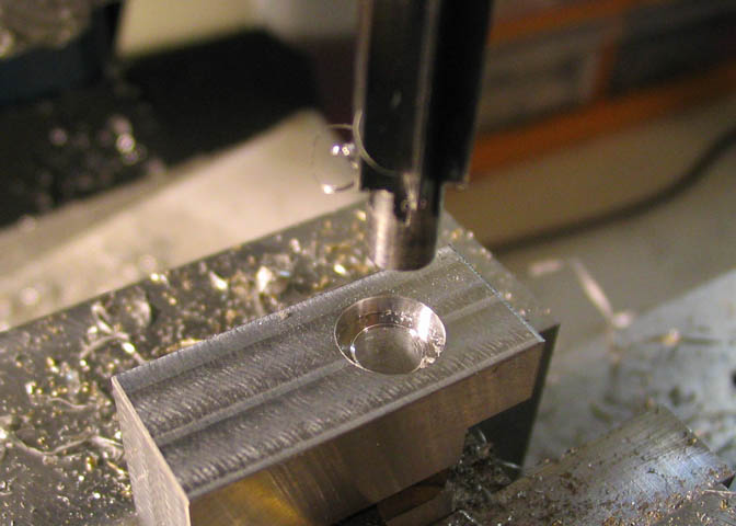
The last step in this piece is to drill and tap the set screw hole to hold the DI shank.
When you tap a hole, it always brings up a little bur, like in the picture above. If you're going
to file all the surfaces, that won't matter so much, but I'm leaving the edges on this "as
milled", so the bur needs to be removed.
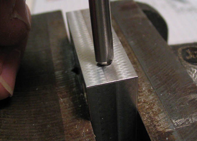
The hole is too small for a regular countersink to clean up, so a center drill is used to clean it up.
Just turned lightly between the fingers will usually do the job.
(Put a lead shot down in the hole before the set screw is tightened down on the DI shank.)
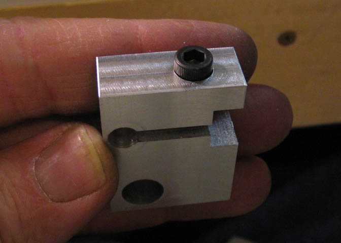
And that part is done.
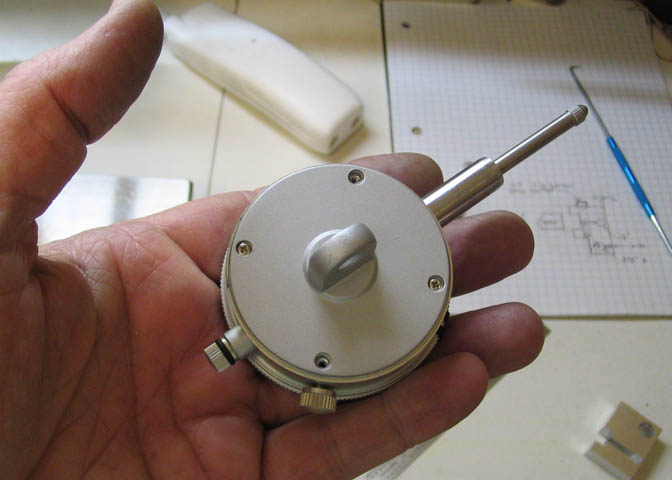
The back of most DI's have some kind of lug. Other wise you would only be able to use it
by holding the shank. Some are like that. This one's not. That lug is just completely in my
way. It won't let the DI set up close to the lathe bed...
So, off with it's head!
These things are held on the back of the DI with four little screws. They are meant to be taken off,
so you can reposition the mounting lug for different mountings. If you want to take one off and look
around in there, go ahead. Nothing will jump out at you.
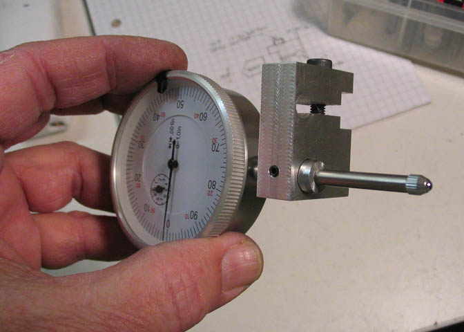
Now it's ready to go to work.
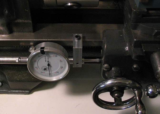
It can be used to hold the DI and get some kind of readings off the lathe carriage.
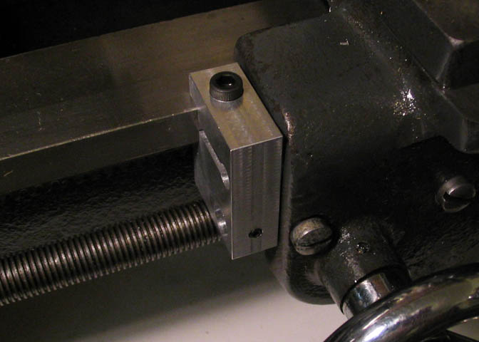
It can be used as a regular carriage stop.
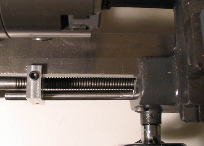
Or a piece of 3/8" drill rod can be put in the place of the DI to use as a rod stop for the carriage.
Back to the Atlas Pages
More Taig Lathe & Mill Projects
deansphotographica.com
(home page)
Copyright Dean Williams