A Tailstock Dial Indicator for the Taig Lathe
I've put off this little project for years. Sometimes, the small things just don't get their due
attention in my shop because of other ongoing projects and paying work. Not enough time!
Finally got around to it. There are a lot of versions of a tailstock dial indicator mount on the
internet. The ones I've seen have the plunger for the indicator facing the head stock, and rely on
the tiny spring inside the indicator to hold plunger tension against a block mounted to the drilling
ram. This one is built the other way around, because I wanted a positive action between the
drilling ram and the indicator, and it also eliminates having that little spring at full stretch when
the tailstock ram is left in the retracted position, as it normally is. I also made it so the indicator
dial faces directly toward the lathe operator, instead of lying flat. The arm that clamps to the
tailstock ram holds onto the brass drill chuck register, so the ram does not loose any travel capacity.
Although I used both the Taig lathe and milling machine, this project can be done on just the
lathe with the milling attachment. You could even do it without the use of the milling attachment
if you used some creative setups and an angle plate.
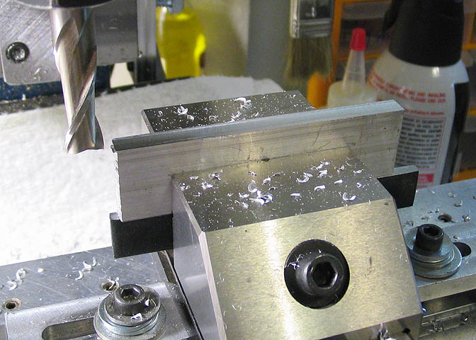
This part will be the arm that mounts to the tailstock ram.
Starting with a piece of 1/4" thick aluminum, it's milled on the edges to bring it to a length
of 2.75" by .8" wide.
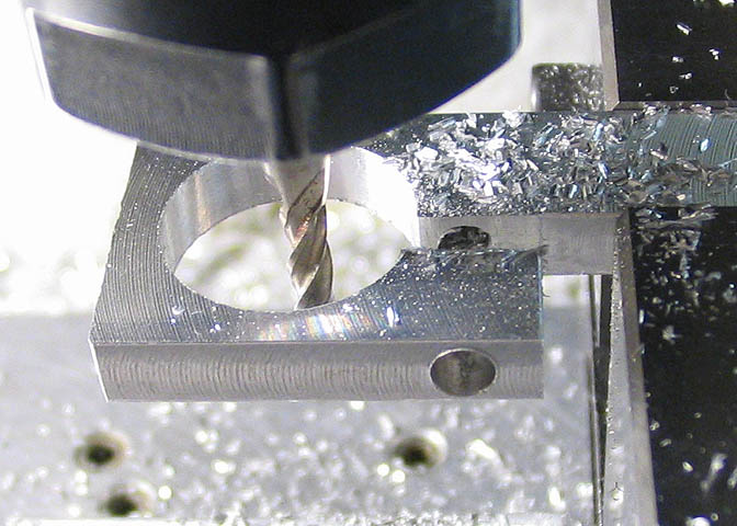
The piece is laid flat in the vise and centered lengthwise under the mill spindle. Move in .400"
from one end and drill or bore a .625" diameter hole to fit on the brass drill chuck register on
the tailstock ram. Measure the diameter of that register before boring this hole, just to make
sure you hit the right size. The one on my lathe is the .625" mentioned above.
Next, one side is flycut a few thousandths just to clean up the surface, and then the piece is flipped
over and the other side flycut to bring the thickness of the piece to .200".
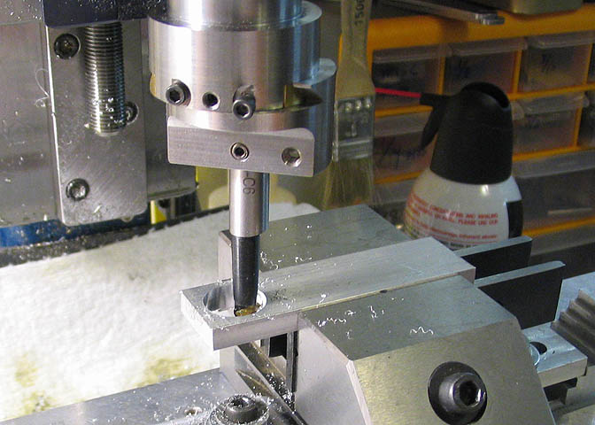
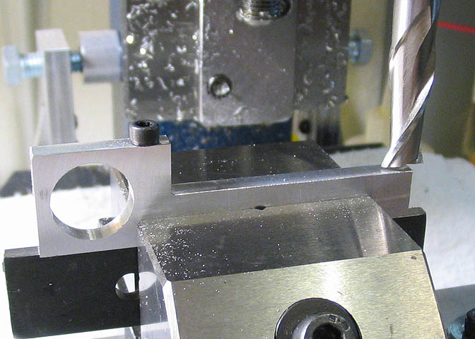
Turn the piece on edge as shown above, center the edge under the mill spindle, and dial in .850"
from the end with the large hole. Drill at that location all the way through with a #35 drill. Then,
drill down the same hole with a #27 drill, to a depth of .400". That will clear the threads for a
6-32 machine screw. Tap straight through the bottom half of the hole for #6-32 threads.
Right now, put a socket head cap screw into this hole, going in through the clearance hole
first, and thread it into the bottom part with the threads. This is just to make sure the next
step gets cut on the correct side of the piece.
Just a note:
My taps in this size happen to be the same body diameter as the 6-32 threads that they tap.
Some taps, depending on brand, may have a larger diameter body than the threads they tap,
and if that is the case with your taps, simply turn the piece over and do the tapping from the
other side.
Put the piece in the vise with the cap screw head facing up. Again, make sure that the un-threaded
part of the tapped hole is UP.
Mill away .400" from the width of the piece as shown, leaving the end with the large hole 1.00" long.
Now, remove the cap screw, and mill a slot so the end can clamp on the brass chuck register
on the tailstock ram. The slot can be any convenient width up to about 1/8". Locate the slot
by touching off your end mill on the surface milled away in the previous step.
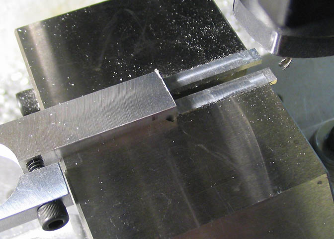
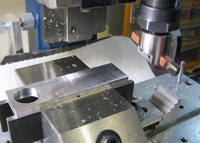
Turn the piece on its side in the vise with the cap screw head facing you, (the machine operator).
Use parallels and shims as needed to position it so it sits above the jaws enough that you can mill
away the upper surface leaving a remaining thickness of 1/16". The length of this milled away
area is .650" long. Finally, mill a slot down the middle of this thinner area. The width of this slot
depends on the diameter of the screw-in cap in the top end of the plunger on your particular brand
of indicator. The one on mine was .080" diameter, and I made this slot using a 7/64" end mill.
Clean up the arm with a file, and it's done.
This piece will be the base mount that holds the dial indicator to the tailstock. Start with a
piece of 1/2" aluminum square stock. Mill the ends to clean them up and bring to a length
of 1.75". Starting .140" from one end and centered in the piece, mill a 3/16 slot clear through
for a length of .350". This will be the clamping hole that mounts the piece using a 10-32
screw and square nut in one of the T-slots in the Taig tailstock.
Check that the screw you want to use for mounting this piece will go into the slot easily.
If it's a little tight, widen the slot a couple of thousandths.
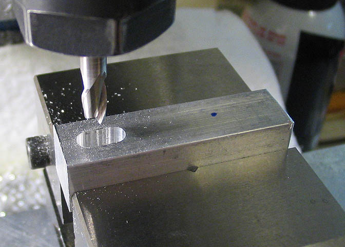
Now, from the same end you measured from for that slot, crank the piece over 1.25" (from
that end), and drill through with a #7 bit and tap 1/4-20. I didn't show that hole, but it will be
where you see the blue dot on the piece.
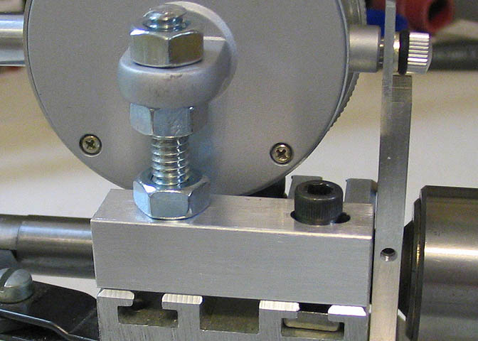
This shows how the block mounts to the tailstock. A piece of 1/4-20 all-thread is screwed into
the hole on the left, and a nut is used to lock it in place. Make the length of all-thread long
enough to give you some vertical adjustment for your dial indicator.
The slot on the right end of the block allows adjusting the indicator to the right or left so you
can adjust your indicator to read at zero any position you like on the dial.
NOTE:
Almost all drop indicators, (what most everyone calls "dial" indicators), have removable backs.
They are made to be removed so you can turn the mounting lug to suit the way you want to
mount the indicator. If the lug on your indicator is facing the wrong way, just take out the screws
around the circumference of the back and lift it off. Nothing will jump out or fly away. They
are made to do this. Take care not to get any debris inside and it will be fine.
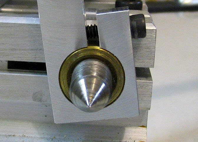
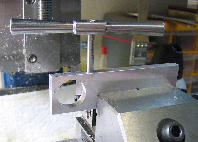
The "arm" piece mounts to the drill chuck register as shown above. Mounting it on the register
means that no travel on your ram is lost. When you mount it, make sure it does not interfere
with your drill chuck seating against the surface of the brass register.
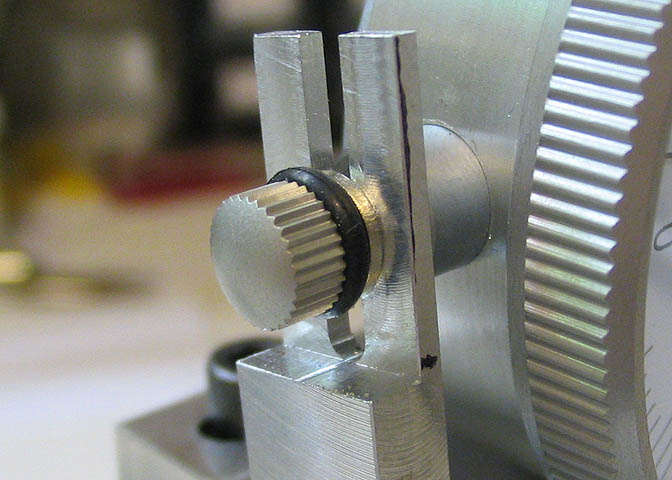
The thinner slotted part of the arm mounts to the top of the indicator plunger. By rotating the
arm on the tailstock ram, and by moving the mounting block slightly, you can get the indicator
lined up and pointing to zero at a position that suits you.
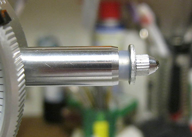
The small knurled piece that you see in the picture is just a plug for the end of the plunger rod.
They are threaded in, just like the standard probe on the other end of the plunger. When you
remove this plug, don't let the plunger sink inside the body of the indicator. It could cause let
plunger rod slip of the little drive pinion. If that should happen, you can put it right by taking
off the back and gently turning that little pinion to re-establish the mesh of the rack on the
plunger with the small pinion, but it is just easier to avoid that in the first place.
I left the slot here quite a bit longer than needed, in case I have to replace this indicator someday.
The diameter of these indicators varies depending on the brand, and specification.
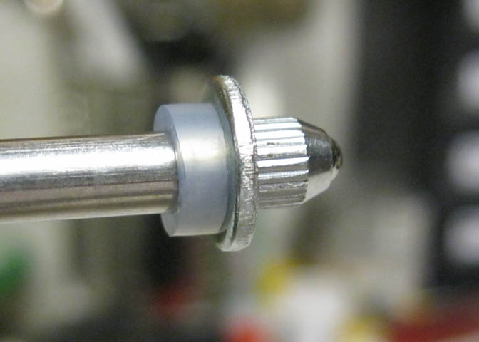
One last thing to do. Put a little piece of silicone tubing or an o-ring on the free end of the
plunger with a small washer to back it up. This will keep the indicator from being damaged
by shock from pushing the tailstock ram to its extremes.
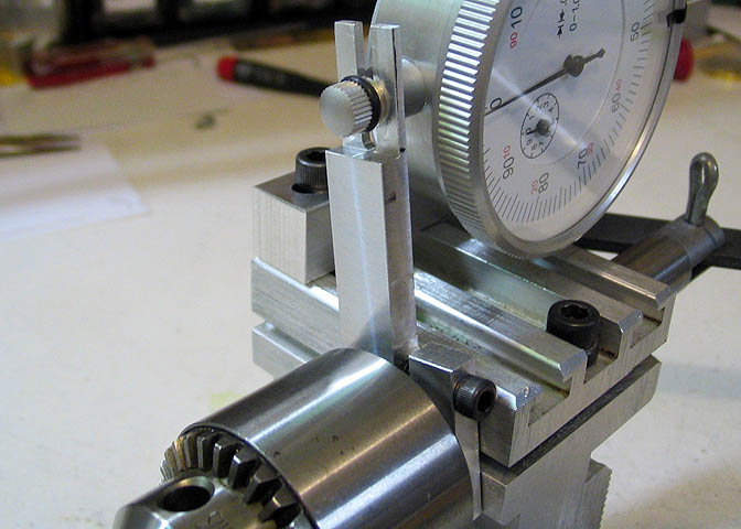
This shot shows the plunger at the limit of its travel. This little "shock absorber" does not
reduce the nominal travel of the indicator. It still has one inch plus.
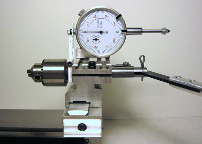
Shown retracted.
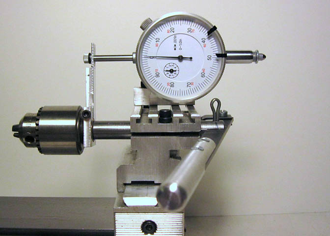
And fully extended.
That's about it. Thanks for having a look.
More Taig Lathe & Mill Projects
Copyright 1998-2011 Dean Williams