Making Multi-Point Gear Cutters
For years I have done all my gear cutting with single point cutters. I've made
a lot of gears in this manner. I don't know how many, but looking over a number
of projects in the shop, it has to be over 100 in all, including a full set of change
gears for a Sherline lathe I once owned. All with single tool point flycutter set-ups.
Well, I have a project planned that will need many gears cut to complete it, and I
figure it's time I took a step up to multi-point gear cutters. They should make my
gear cutting chores much quicker, once I have the set-up for making the cutters.
I found a version for this type of cutter making jig on a clock making forum. This
isn't something I came up with myself, and I'm taking no credit for it. I did take the
time to take quite a few pictures of the project, and thought others might take an
interest in this method, and maybe in some of my comments.
I didn't give all dimensions for the jig and cutter blanks They can be made to
suit individual needs, and dimensions adjusted as needed.
(Note: This is an addition to my initial publication of this web page.
I have been informed that the original write-up for this type of cutter
was written by David Creed, and that a similar tool construction article
in book form was written by J. Malcolm Wild. The only other credit I found
in the original article I read, the one I understand to be Mr. Creed's, was
to David Robertson. If there are other credits due, I will be glad to
include them at any time they become evident.)
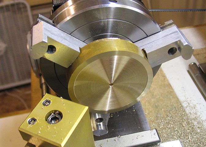
I started with a piece of 2" dia brass, about 5/8" thick. I faced one end, then cut
a recess about .010" deep from the center out to within about 1/4" from the edge
to let the base sit firmly without any wobble.
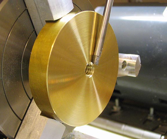
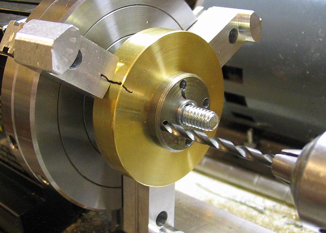
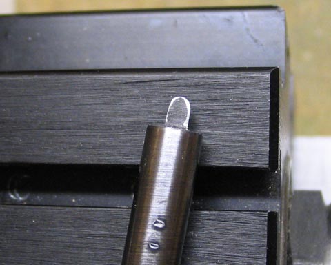
I turned the base over, faced it, and spotted, drilled, and tapped for 1/4-20 threads.
The small rod pointing to the tapped hole is showing the small chip that is raised
when tapping a hole. This must be turned off so the surface of the base plate is flat.
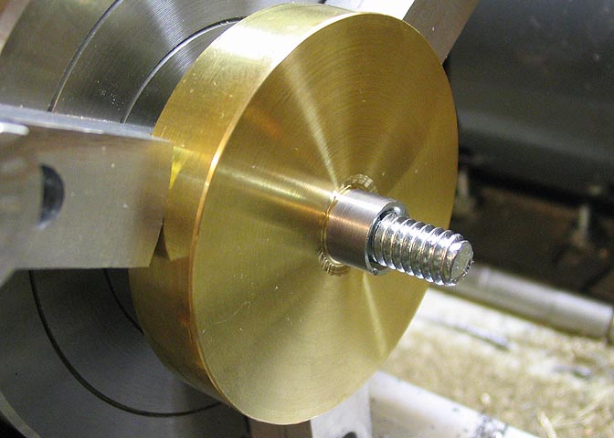
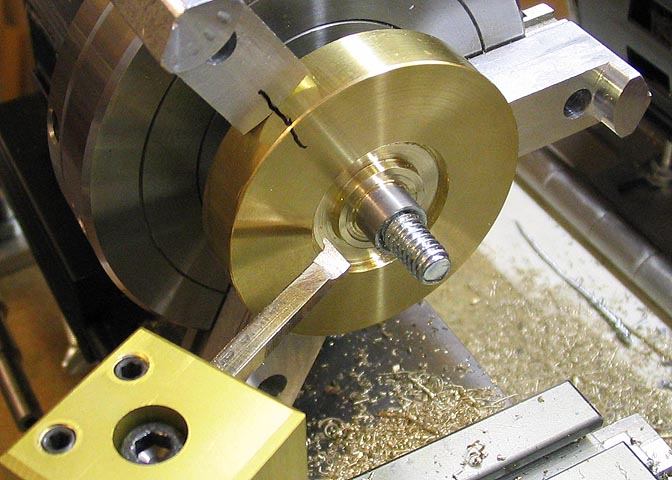
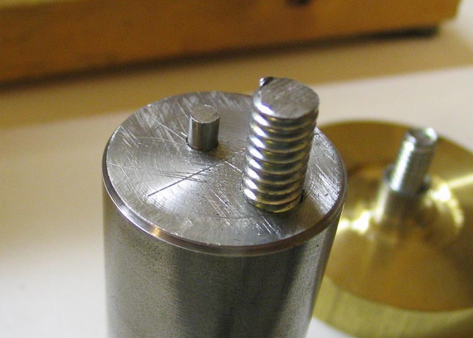
Now a 1/4-20 stud is threaded into the hole and a nut is run down against the
surface of the base plate. Locktite is used on both stud and nut, and tightened
down snug. Let the Locktite cure, then turn the nut down to produce this locating
shoulder, as shown. You can use what ever diameter suits you for the shoulder,
but it should be something convenient, as you will have to bore each cutter blank
you make to this dimension. The arbor you use to mount the cutter will have
to be this size too.
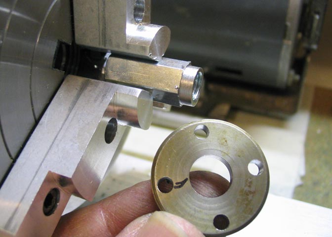
Now the cutter drilling template is made. Four holes are drilled in a disc
of a suitable size to accommodate a hole pattern radius of 3/8", and the center
of the disc is bored out for a close fit over the turned down sleeve of the
brass drilling base, (previous picture).
Put the drilling template over the base shoulder stud and spot a hole deep
enough to let you insert a cutter for the next step.
Turn a recess in the base about .15" deep and wide enough to allow your 1/8"
drill bit to clear when you drill the cutter blank. I used a boring tool to make
the corners of the recess square, but it's not necessary.
Turn a mounting nut with a shoulder that will fit the hole your drilling template.
This will keep the template, and later, the cutter blank centered during later operations.
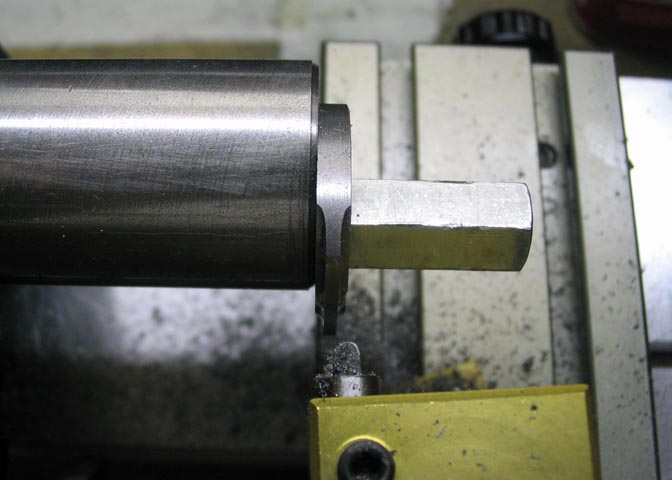
Drill and tap a 1/4-20 hole .250 off center in the end of an arbor that will fit your lathe.
This is for a Taig lathe, and the same arbor will fit Sherline. Both these lathes have a
spindle thread of 3/4-16, but if you have a different thread on your lathe you will need
to make what suits you.
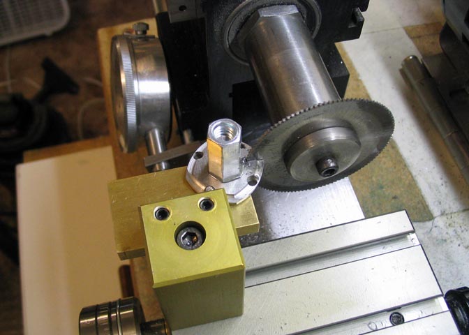
Once you have the tapped hole in the end of the arbor, screw in a stud that will leave
about 5/8" of threads above the surface. Locktite it in. When the Locktite has cured,
put your drilling template on the stud and tighten and center it with the shoulder nut as
shown. Then drill through the template hole at the 12 o'clock position, 3/8" deep, 1/8" dia.
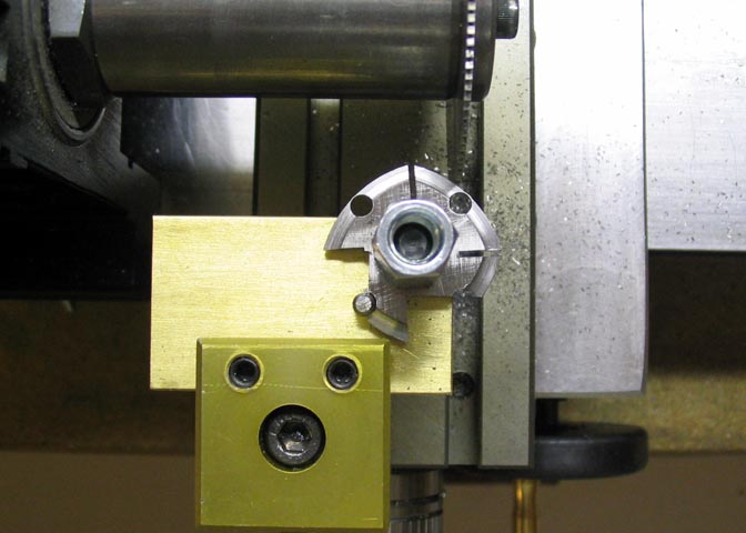
Drill the hole completely through the remainder of the arbor using a 3/32 bit so you can
punch out the stud that will go into the hole, if needed.
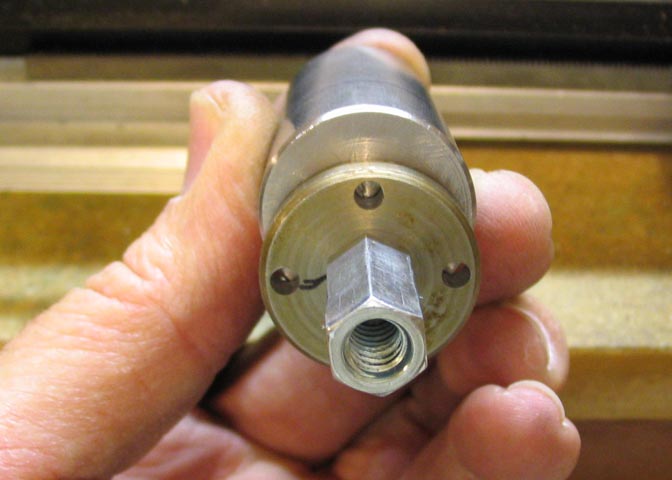
A 1/8" piece of drill rod is now put in the hole with Locktite. The drill rod stud needs to
stick up above the surface just under 1/8".
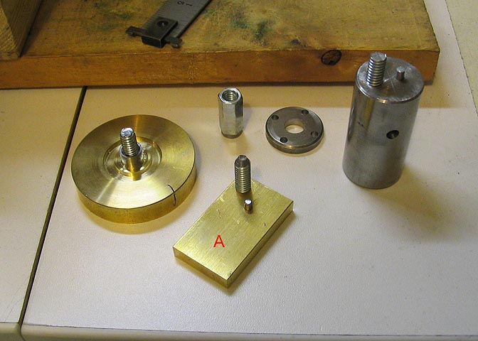
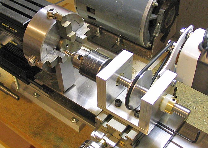
These are all the parts you should now have, with the exception of the part labeled "A".
Make that part after you have your first cutter blank made, so you will know where to position
the holes for the studs. It is made the same way as the arbor shown in the previous picture.
This square piece is cut from a strip of 1/8 x 1" O-1 tool steel, un-hardened,
of course. A hole is bored in the center of it to match the sleeve on the
drilling jig stud.
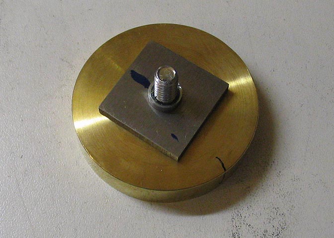
Place the drilling template over the piece of tool steel, which will become your cutter blank,
and tighten it down. Drill the tool steel at each of the holes, 1/8".
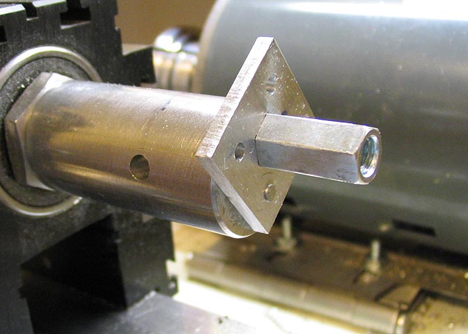
Mount the cutter blank on the turning arbor and fasten it using the shouldered
end of the coupling nut to keep it centered on the arbor stud.
This shot shows the cutter blank with two of the corners rounded. You must take
note of your cross slide reading after you finish the first cut on the blank, and
repeat that setting for each of the remaining three sides of the piece.
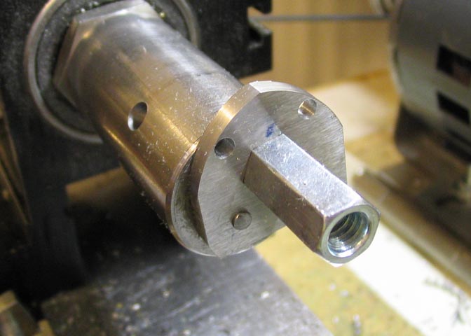
This is the blank finished out, and ready for what ever profile is to be cut.
I dulled two cobalt HSS bits cutting the first blank, and switched to plain HSS
tools. I was kind of surprised that the HSS cobalt bits dulled so quickly.
As soon as they start to dull, they will work harden the blank almost immediately.
If the piece does work harden, it will dull a fresh tool no matter how sharp it is. If
the piece becomes work hardened, remove the piece, arbor and all, and just a
touch against a grinding wheel will remove the hardened spot.
I used a fresh tool to remove the last couple of thousandths of each
facet after all facets are roughed out.
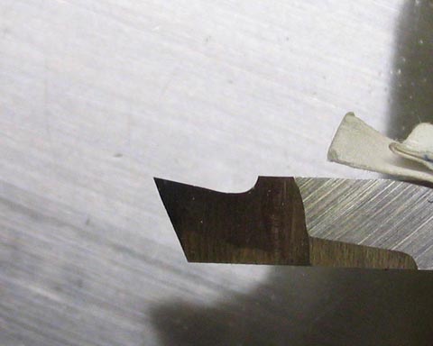
I found that a well sharpened plain HSS tool bit with a slight hook worked
better than the more exotic alloys. Kind of like this.
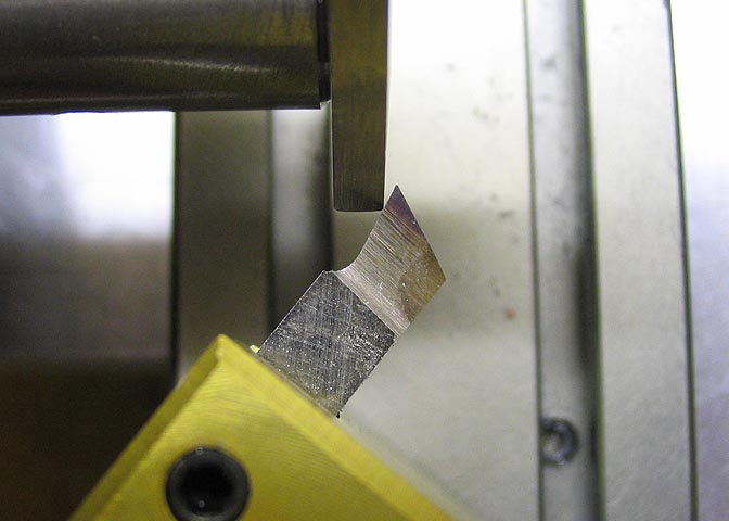
Also, if the tool is fed into the work at
an angle that did not let the work piece strike the very tip of the tool it
prevented chipping the tool point and work hardening the cutter blank.
This is an exaggerated view of what I mean, just so you can see
what's going on.
A lube like Tap Magic, a cross slide feed of about .010, and a speed
around 500 rpm seemed to work best. If you can reduce the speed
of your lathe to about 100 rpm you may be able to eliminate tool
chipping and work hardening troubles.
Now that the cutter blank is formed a tool is made to cut the gear profile
into the cutter. This cutter will be for a module gear profile, which are used
mainly in clock gears. Involute gear profiles can be made in a similar manner.
I start here with piece of 1/4" water hardening drill rod. For this particular
cutter, the dimensions mentioned here are for a Module 8 wheel (gear).
Different size and types of teeth require different tool dimensions, but
the process is the same.
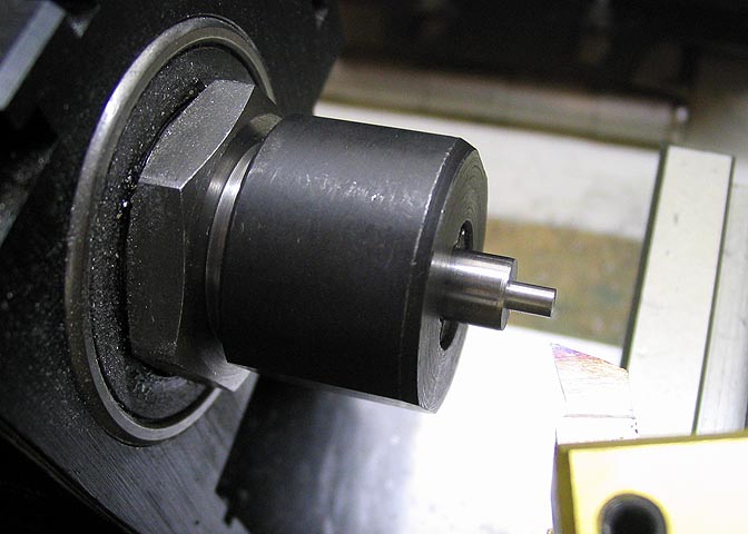
In this case, I need a tool that will cut a radius of .049", so here I have turned
the drill rod down to .098 dia for a short distance that will become the tool
bit end.
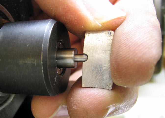
I used a gauge to judge the ball on the end of the tool. The gauge is a
piece of 1/16" aluminum sheet with a .098" hole drilled through it, and
then the piece is cut in half and filed smooth. Not having a ball turner, I
used a file to round the end into the shape of a ball, using the gauge plate
to judge when I had the correct radius on the end of the tool.
Now 1/2 of the tool bit end is ground off so there will be a sharp cutting
edge left. The way to know when you've ground down to half the diameter
is to measure from the flat spot that is produced by grinding, to the
outside of the remaining diameter of the tool. In this case, I started with
.098". I ground it down until there was .049" left and that's it.
Once ground to the proper shape, the bit is heated to bright red heat and
quenched in luke warm water. It's then polished and again heated, this time
hopefully to a straw/yellowish color, and again quenched.
It's pretty hard to catch really small pieces just as they turn to a straw
color, (at least for me). This one ended up a bit blue.
The final step is a light honing, and it's ready to cut.
I made a test cut on one of my cutter blanks to check that I had the
tool bit ground properly. When I was satisfied, I put in a new blank
and first cut all of one side of the cutter blank, then reset the carriage
and cut the other side. Careful notes of feed dials need to be kept
or you will end up with a gear cutter with teeth of differing widths.
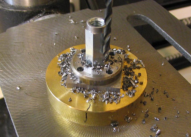
Once all the facets are cut the blank is put into the cutting jig and the
waste material is removed. A portion of each of the jig holes in the
cutter must be left for future sharpening of the cutter.
Here you can see the removal of the waste, and the partial
jig holes left in the cutter.

The cutter is removed from the jig, and deburred.
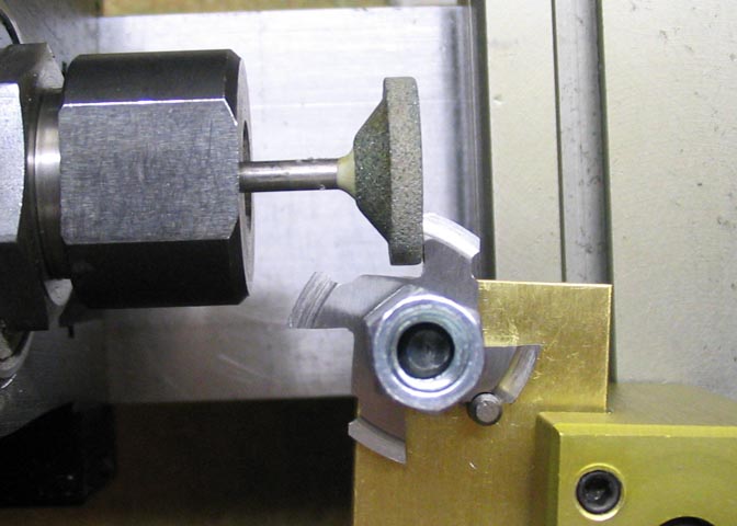
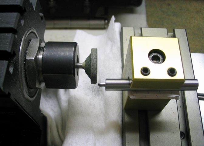
The final step before hardening is to grind the cutting faces
on each tooth. Lock the carriage and just use the cross slide
to feed each tooth into the grinding wheel. You only need to grind
enough to remove tooling marks. This is the same
way the cutter is re-sharpened when needed.
Don't forget to cover the bed/ways on your lathe when grinding!
The final step for this cutter is hardening and tempering and
it will be ready for use.
More Taig lathe projects
deansphotographica.com
(home page)
Copyright 8-2008 Dean Williams