A Miniature Lathe Chuck
Part 1
A friend of mine collects small engines and machine tools. He recently got a small model lathe that
didn't come with a chuck, so I offered to make one for him. The lathe he got is a working model,
and not very big. He said a chuck of about 1" diameter would suit it well.
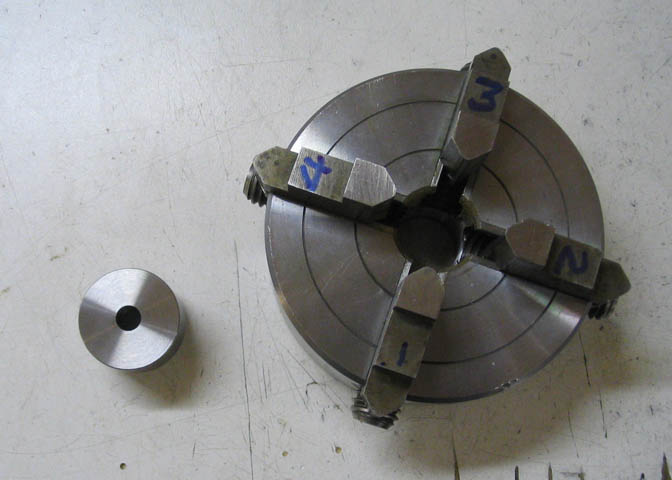
I started with the basic chuck body, which is mainly a round thing with a second smaller diameter on the other
end where the spindle threads will go. Here, it is shown next to my standard Taig four jaw independent chuck, and
it will be built similar to that one. The Taig chuck is about 3.2" diameter, and the miniature for Kenneth will be 1".
You can see the threads inside the back side, and the part that has those threads comes out the back parallel
to the front chuck surface, so that back part can be used for the needed chuck register. (The chuck register
is a part that is meant to mate up to the spindle and keeps the chuck true each time you take it off the spindle
and then put it back on.)
I stopped at this point to work on a new spindle for Kenneth's lathe. The spindle that is on his model lathe
now has no register surface, so I want to make him one that does. Making a new spindle for his lathe will
also help me to get the new chuck made, as it will be handy to have something it mates up with in order to
get the chuck running true.
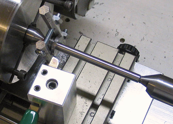
In the pic above, I've turned down a diameter that will take the M12 x 1.5 threads, which is the thread on Kenneth's
small lathe spindle.
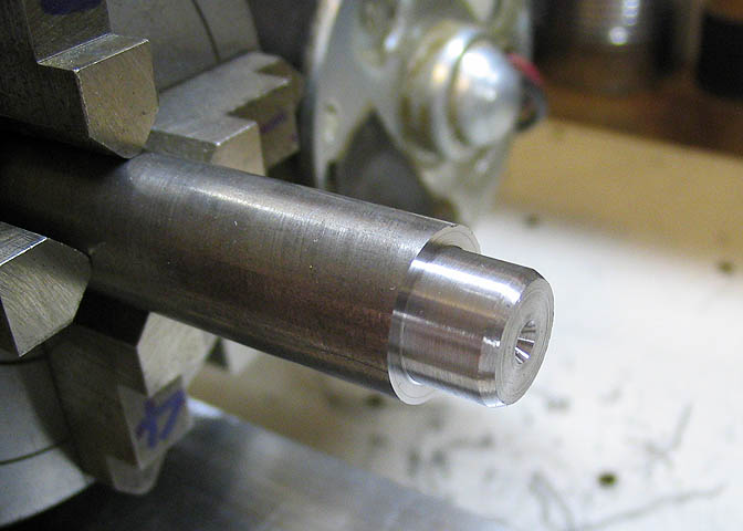
A bevel is put on the end that will take the threads to help start the die straight, and to make a nice start
of the threads when they are completed. You can see here that I've center drilled the end of the piece. The other
end got the same treatment.
The next step is to run the die over this part on the end. I didn't take pics of that bit.
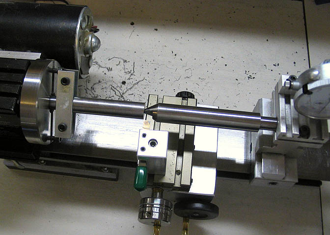
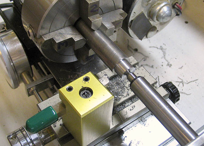
Now the piece is mounted between centers. The threads can't be seen here. They are under the two metal strips
next to the drive plate on the lathe.
I've changed the drive clamp here because it was getting in the way. You can see that it's clamped on the
threads of the new spindle. Both ends of the piece are supported between centers on the lathe and the final
diameter for the new spindle is turned down. If you need top accuracy from your lathe on anything that is
over a few inches long, the very best you can do is to turn between centers. Nothing else will be as accurate.
In the olden days, before most of us were born, turning between centers was one of the only options.
There were somewhat crude chucks back in those times, but they were not used when precision work was expected.
Nowadays we have lots of work holding options for the lathe. Even more than most people know of, but still,
turning between centers is the most accurate way.
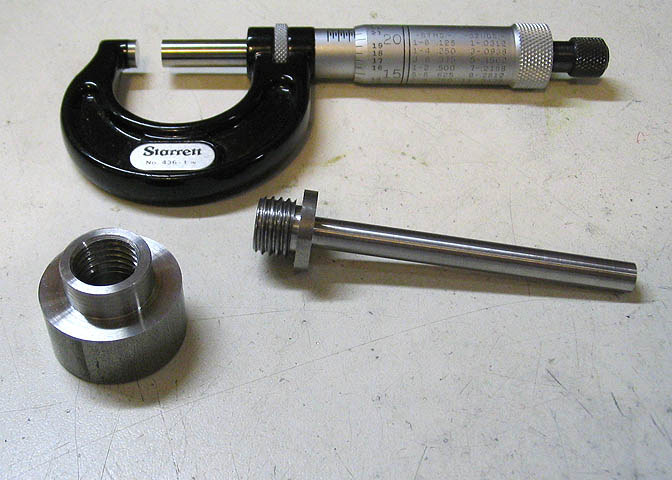
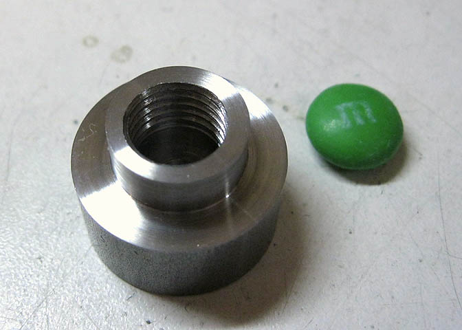
Here is the new spindle, along with the blank for the new chuck body.
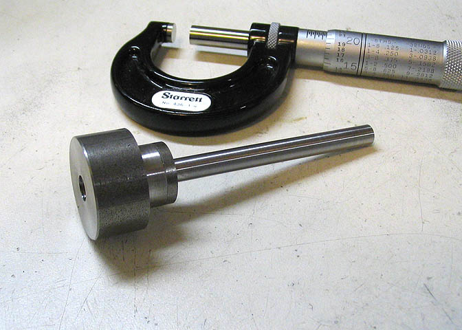
One more shot, showing the chuck blank mounted to the new spindle.
Now it's time for some serious work on the chuck body.
I put it in my lathe chuck and checked the runout of the piece on my lathe, making minor adjustments until
I got under a couple thou on the runout. Then transferred my lathe chuck with the piece onto my small shop
built dividing head that had been squared up on my mill. Indexing the piece at 90 deg intervals, it was
first spot drilled, then drilled for the tap size I wanted to use.
Then the four holes are tapped 8-32 for the adjusting screws that will move the chuck jaws.
After tapping these holes, I removed my chuck from the dividing head to have a look at the progress. Screwing
in four 8-32 screws I could see they were very slightly off center by looking in the hole in the center of the
mini chuck. Rats! Everyone makes mistakes. Everyone! I couldn't figure out how this happened, because I
was quite careful while setting up the dividing head on the mill. It shouldn't be off!
What happened was not a goof in setting up the piece, as I thought it must be. I found that one of the dials
on my mill was slightly loose. I had just had the dials off to clean some crud that had built up behind them,
and when I replaced them I had not got one of the friction rings tight behind one dial. Those dials tell you
"where you are" on your mill table, and the one that I had not got tight had rotated on its own as I was
cranking the table, giving a false reading. All my fault, but not in my setup work. In my maintenance work!
Well, I got that dial put back on correctly, then re-checked all my settings. I didn't want to start over on
the piece, so I used an end mill to re-bore the holes for tapping. A drill bit wouldn't work, since they
flex a lot and would have just followed the old hole crooked. I happened to have an end mill just the right
size for a 10-32 tap, so used that and re-tapped the holes slightly larger. It worked out well in the end, as
I decided the larger 10-32 screws were a better size anyway. A rare case of a mistake working out for the best.
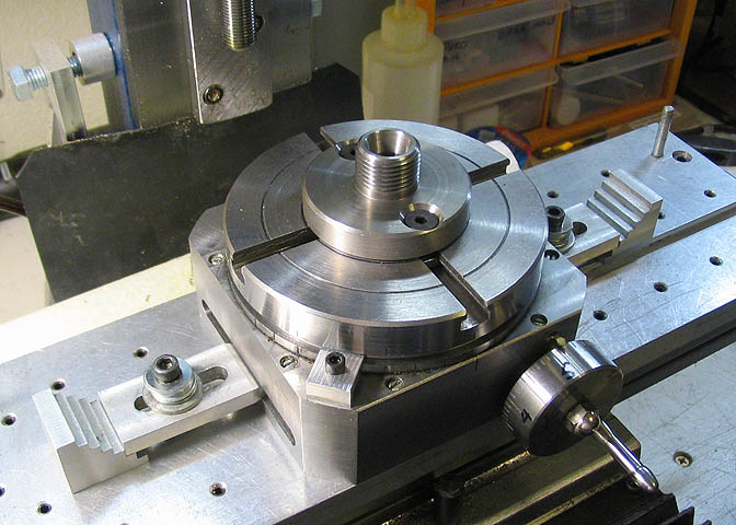
Now I need to get set up to mill the slots in the mini chuck so it will take the four jaws. I have an adapter
that mounts to the rotary table so the table will take the chuck for my lathe. The rotary table and adapter are
centered under the mill spindle using a specially turned shank that fits tight through the adapter and into a
hole in the rotary table. Then that shank is lined up so it fits tight in the spindle of the mill.
The adapter is made by Taig. The rotary table is something I made here in the shop, and you can
read about it if you like. Go to the main page link at the bottom of this page.
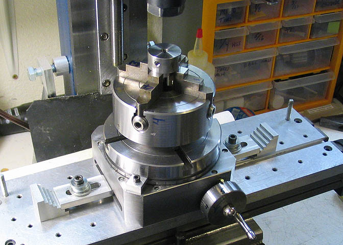
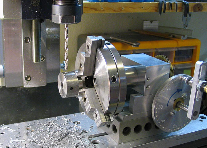
After mounting the body for the mini chuck in the four jaw chuck for my lathe, it is screwed onto the rotary table.
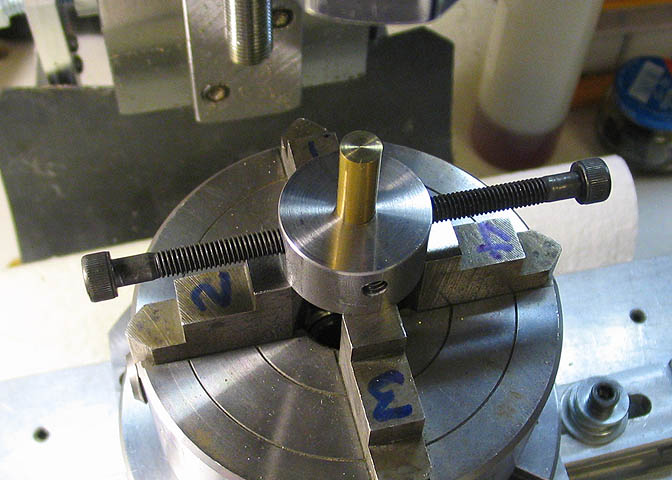
To index the mini chuck so that the slots for the jaws will be at 90 deg, I put a brass plug in the chuck
blank, then screwed in some long 10-32 cap screws. The brass plug lets the screws get tight, so they are
pushed out against the threads in the side of the chuck body. This keeps them straight.
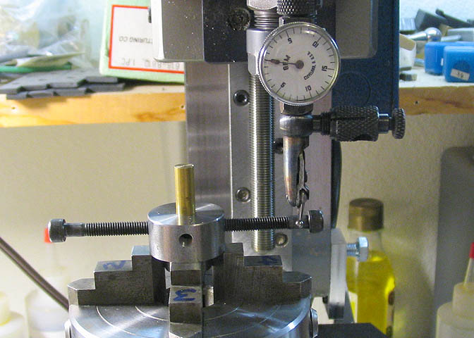
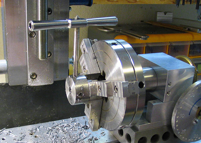
Then I can indicate off the shanks of the two screws, first on one side....
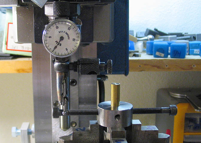
....then on the other side. The rotary table is turned slightly one way or the other until I get the
same reading on each of the two screws.
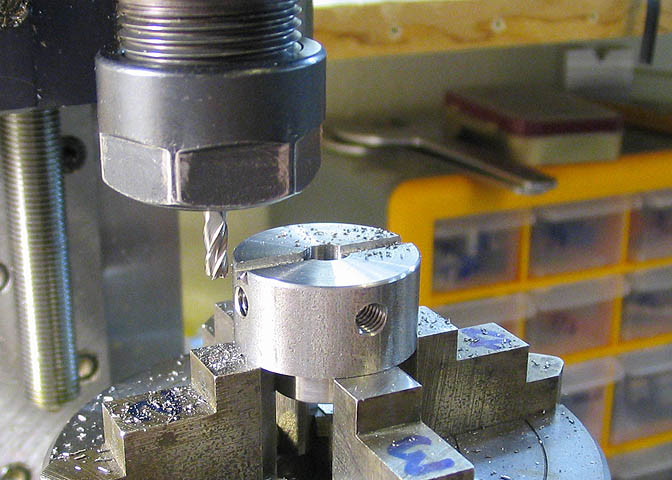
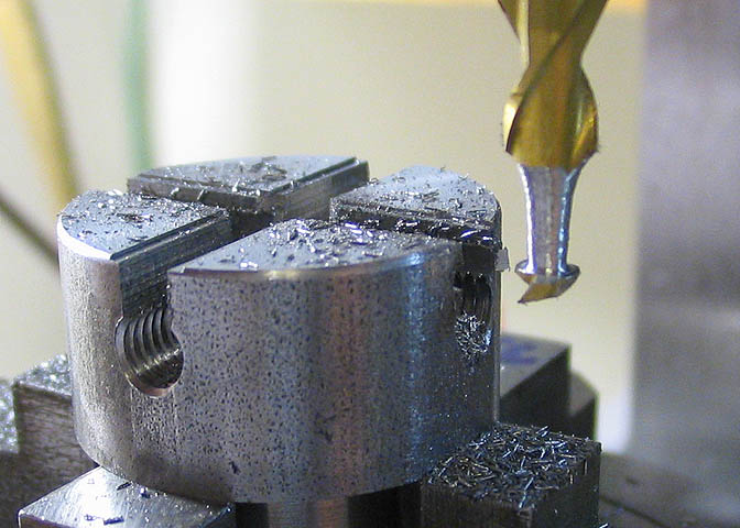
First milling cuts go through the top of the chuck body, and down into the holes for the tapped threads.
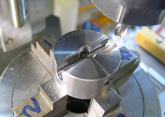
Second milling cut is with a larger end mill and makes a shallow recess in the top of the chuck body that
will let the chuck jaws slide across the top of the chuck without wobbling side to side. The jaws will
be the same width as that top slot.
Then the rotary table is turned 90 deg and the same thing done again.
There is more to do to finish the chuck body.
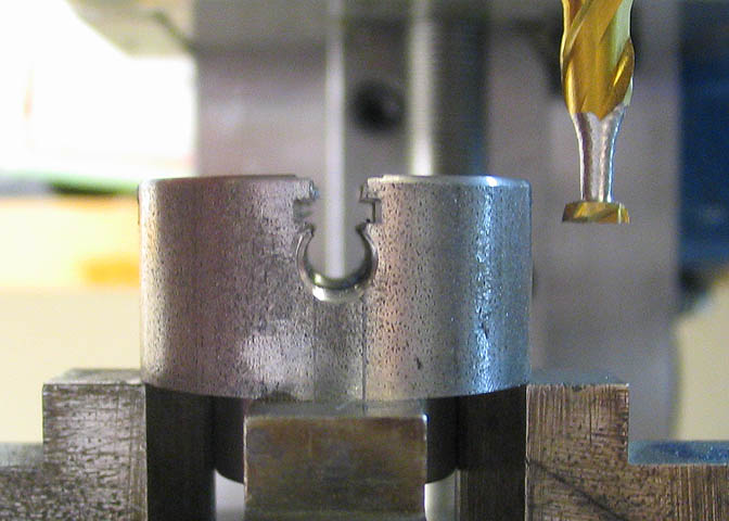
For the next step on the chuck body, I need to cut a slot inside the chuck kind of like a T-slot.
Usually, for a tool to make a cut like what I need, I just make the tool out of drill rod (silver steel),
then harden it and hone on the cutting edges. For the tool here I'm trying something different. Instead
of making a complete tool, I'm going to try grinding an end mill to the shape I need.
A while back I bought a lot of 10 cheapo Chinese end mills. They are brand new, but after trying one
I find they are quite inferior for making a good finish, so I've only used one of that lot of 10, and
the rest I tossed into a junk box. I'm not happy with them at all! I figured I have nothing to loose
in hacking up a new one of these to see how it does for this job.
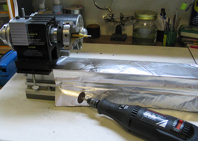
This involves grinding down the end mill flutes in the lathe. I covered the lathe bed with tin foil
to protect it from the abrasive dust made with the grinding wheel. Then I got after it with the Dremel.
The lathe was run at a couple hundred RPM and the Dremel was set to 5000 RPM. Safety glasses on, and
start grinding.
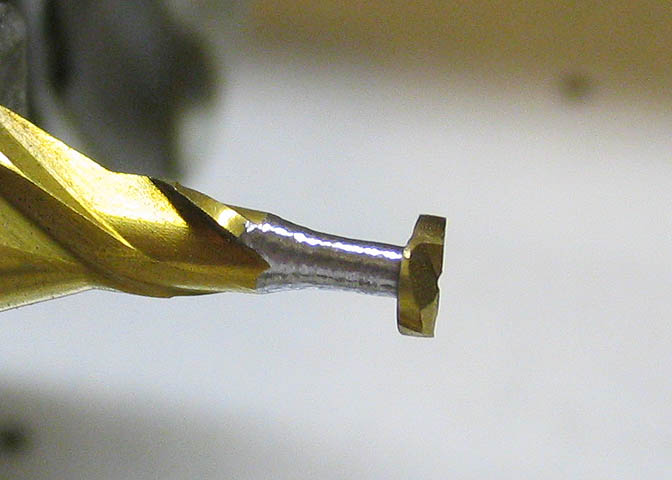
When I got done with it, I had this thing, which is shaped much like a T-slot cutter, 3/16" diameter and
.055" wide. It only took about 10 minutes, which is a lot faster than making the tool from a drill rod blank.
After I was done, I completely disassembled that chuck on my lathe and cleaned it in solvent. Cleaned the
whole lathe, too. I do not like grinding on the lathe. The dust gets everywhere and it's very abrasive.
Bad for bearings, lathe ways, scroll chucks, and all that.
I would never do this on my Atlas lathe. It has exposed bearing ends and I'd have nightmares about it.
The Taig lathe has sealed bearings, but it still bugs me some. It's a normal thing to do on a lathe for
highly finished things like camshafts, or even a lathe spindle. I'm not saying you shouldn't do it, but
you must clean up after yourself very well afterward if you want your machines to last.
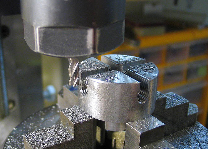
With the new cutter ready to go, I can cut the slots inside the mini chuck body. It worked pretty well,
and now I know what to do with all those crummy new made in China end mills I bought.
Another view of the slots for the jaws.
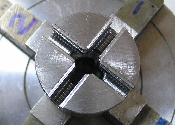
Here's a view looking down so you can see the threads inside the jaw slots.
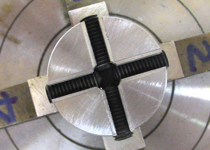
And showing how the jaw screws go in. The screws have to be modified yet, so they will be able to
move the jaws as they are turned.
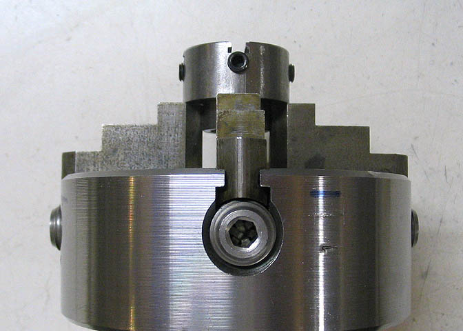
I think if you look at the screw in the large chuck and the screw in the small chuck that you can see
the similarities in the two chucks. Slightly different, but they will work the same.
Please click on the link that says "Part 2" for the finish on this mini-chuck.
Go to
Part 2
To go back to the main projects page, click the link below.
More Taig Lathe & Mill Projects
Copyright 1998-2012 Dean Williams