Making a Leadscrew for the Taig Lathe
There are a lot of articles out on this subject. I've looked at quite a few
of them myself, but I didn't find one that did it just the way I wanted, and
from the many different designs, it looks like a lot of people have their
own idea of just what it should do, and how it should be built.
One idea I found useful was a way to attach the leadscrew mounts to
the ends of the lathe. This came from J.R. Bentley's impressive web site.
You can read more about his projects here.
The main object here is to have a leadscrew, of course, but I had a
few conditions I wanted met, if possible.
I want it to work as it should. One turn of the hand wheel would advance the
carriage .050", just like with the cross slide and compound slide and I want it
to advance in a logical manner. In other words, I want to be able to turn the
hand wheel in the proper direction and have the carriage move in the
direction it should, the same as the cross slide and compound slide.
So to start I need a left hand screw with a pitch of 20 TPI , and a similar half nut.
Also, and this point was something I felt I couldn't do without, I want
to be able to remove the carriage from the lathe the same as with the
unmodified lathe. Once I had the leadscrew assembled and mounted,
I didn't want to have to take bits off of it to slide the carriage off the end
of the lathe bed. I find this feature to be very convenient in a lathe with
a short bed, like the Taig. If you can't take the carriage off the bed, it makes
it less convenient when setting up a long work piece that needs to be
supported by the steady rest.
One of the things peculiar to this version of a leadscrew is that it does
not use a split half nut like other leadscrew conversions. It does use a
half nut of sorts, but it's really just a block with 1/2 the diameter of a thread
cut into it. The pressure of the half nut against the screw is backed up by
a brass runner against the lathe bed extrusion and that brass runner
acts as a wear plate.
For this project, I got a two foot length of 1/4-20 left hand threaded rod,
and a 1/4-20 left hand tap from Enco tools. About $7 for the tap and
$3 for the threaded rod.
The first step is to mount a flat piece into the end recesses at the head
and tail of the lathe bed. I used 1/4" thick aluminum and attached them
with one screw at the front of the lathe and two on the back side. There
is little room for the screw on the front, and it needs to be positioned so
it will not interfere with the carriage or the pinion for the carriage rack.
There is less to interfere on the back side of the bed, so two screws are used.
I used 6-32 in front and 4-40 in back.
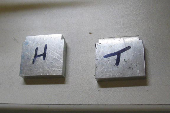
On my lathe, the recess in the head and tail ends are slightly different so
I marked the two pieces for identification.
Drill the mounting holes in each end of the lathe, then put the mounting
plates in place and mark them for drilling and tapping, shown above.
A tip for tapping aluminum, especially if it is one of the gummy alloys:
Using paraffin wax, rubbed on the cutting surfaces of the tap will make
it easier to break the chip when you reverse the tap. With small taps,
like 4-40, advancing the tap only about 1/2 a turn, or less, then reversing
the tap to break the chip will make it much less likely to break your tap.
Clean the hole often when using small taps.
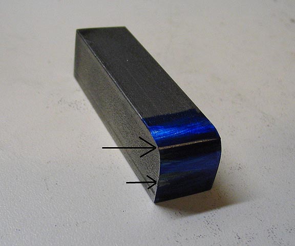
For the end blocks that will be bored for the leadscrew, I used 1/2" square
CRS. One corner is ground to a radius to clear the carriage, and filed to
final shape. To help in finding where the carriage may be rubbing on the
end block, coat it with bluing and run the carriage over it. Where ever you
see shiny spots in the bluing, file a little more, re-blue, and repeat until the
carriage will pass over the block without rubbing.
Once everything looks right, mount the end block to the lathe end. I used
10-32 socket screws, and made sure the block was up tight against the
bottom of the ways.
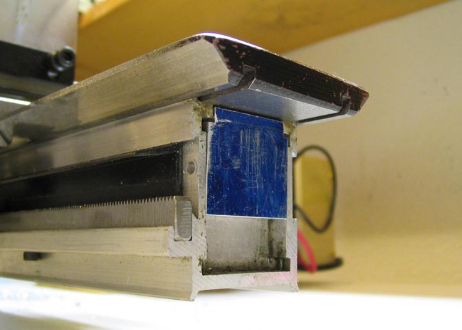
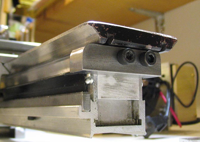
The block for the head end is a little easier, as the carriage does not pass
over the top of it. Grind the radius to your liking and mount as with the tail end.
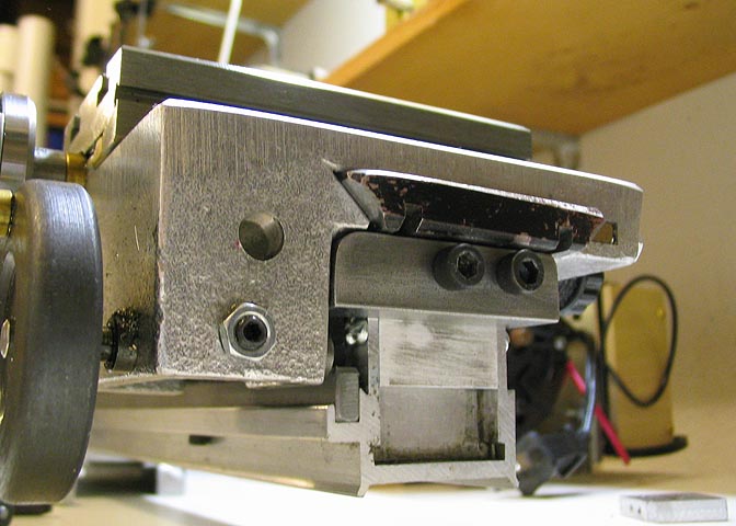
Here you can see that the carriage can pass over the top of the end block,
and can be removed the same as on an unmodified lathe.
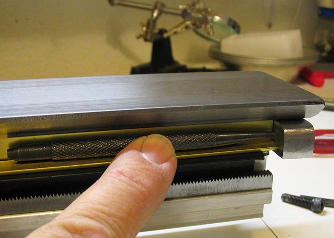
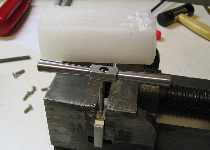
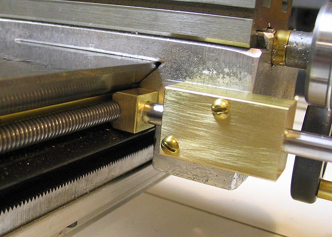
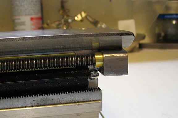
The leadscrew will run against a brass runner that sits against the lathe bed
extrusion directly under the bed ways. You can see the runner here behind
the punch. At this point, a punch of 1/4" diameter is being used to locate the
leadscrew bore in the end blocks. There is also a brass shim beneath the
punch to hold it up off the rack guard as the hole is located. This will provide
clearance for the leadscrew once it is mounted, and keep it from rubbing on
the guard, once the bottom shim is removed.
You must use a punch with a body diameter of 1/4" for this method to work. If
you use a punch of a different diameter, the hole for the leadscrew will be in the
wrong place. If you don't have such a punch, you can make one easily out of
1/4" drill rod. Make a point on one end, and harden and temper to blue. You
only need to harden about 1/2" of the end of the rod. Make sure you temper it
after hardening. If you don't it will probably shatter at the tip with the first sharp blow.
Do this for both end blocks, then remove them and center drill the punch
marks. Then drill through to a diameter appropriate for end shaft of your leadscrew.
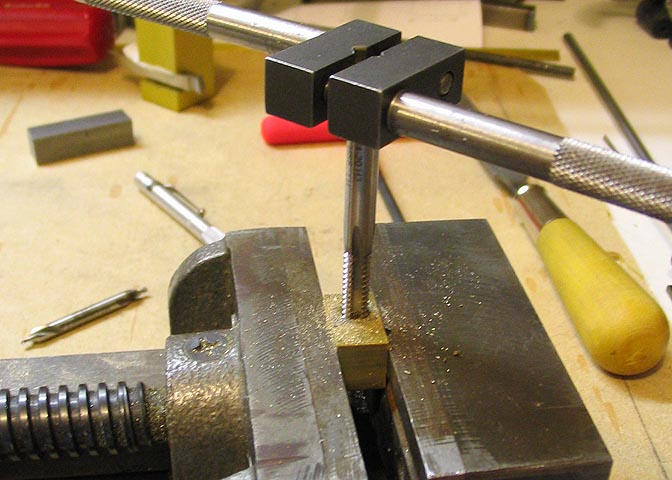
This will be the half nut. To start, it is a piece of 1/2 x 3/4 brass stock. Drill
a #7 hole, centered in the 1/2" dimension and 1/4" from the end of the block.
Then tap the hole with a Left Hand 1/4-20 thread.
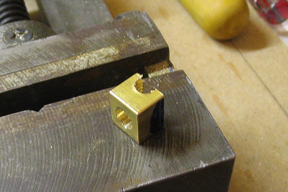
Now cut off the short end of the threaded piece, leaving a little more than
half of the tapped hole. Mill or file off the face of the block that shows the
half thread until it will fit snug (not tight) when pressing it onto your piece
of left hand leadscrew rod.
Drill a 1/4" hole into the back of the half nut block, as deep as you can,
but do not break through into the threads on the other side of the hole.
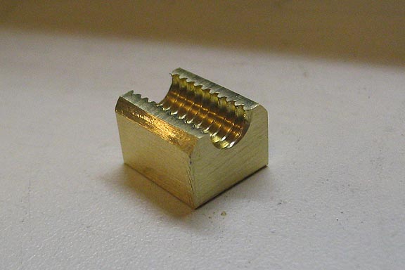
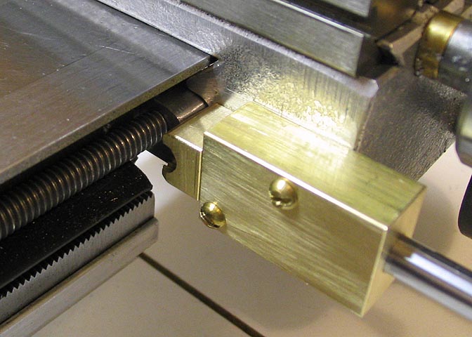
When done it should be something that looks like this. Notice the edges
of the block are beveled with a file, so they will not rub on the rack guard
or the underside of the lathe bed or carriage.
This is the first part of the assembly. You can see the brass runner behind
the leadscrew. It is simply a piece of 3/8" x .040 thick hobby stock.
Push the half nut block onto the screw and make sure you
can take it back off easily. If you can't, file down the threaded side a little more.
This next thing is the block that will mount the half nut assembly to the lathe
carriage. It is 1/2 x 3/4 brass, 1 1/2" long. Drill and ream lengthwise and
centered. The bore through this block should be the same size as 1/4" drill
rod. Since the hole is 1/4", and the drill rod is 1/4", you will probably have to
polish the rod down a little with 600 wet/dry sand paper. Just polish until the
drill rod will barely go through the block without getting stuck. You want a close
running fit. You want a piece of drill rod about 2 1/2" long to start with.
You can make it shorter later, once you get everything fitted up like the next photo.
Mount your piece of drill rod into the hole in the back side of the half nut with
Threadlocker. Make sure it is square to the half nut. Put the shaft through the
block, engage the half nut with the leadscrew threads, and while holding the
block against the carriage, scribe a line that will mark the top surface location
of the block. Bluing the side of the carriage will make the line easier to see.
Once that is done, retract the half nut and shaft into the block so the half nut is
flush with the surface of the block, then slide the carriage down to a position
over the leadscrew end block at the tail of the lathe as in the next photo.
When you have everything where you want it, making sure that the half nut
will clear the end block, scribe another line at the front of the large brass block,
and you will have the location of the block.
Drill holes in the brass block at two places that will give you
locations for tapped holes in the carriage. Then transfer these locations to the
carriage using the marks you scribed on it previously. I drilled mine for
a 4-40 tapped hole.
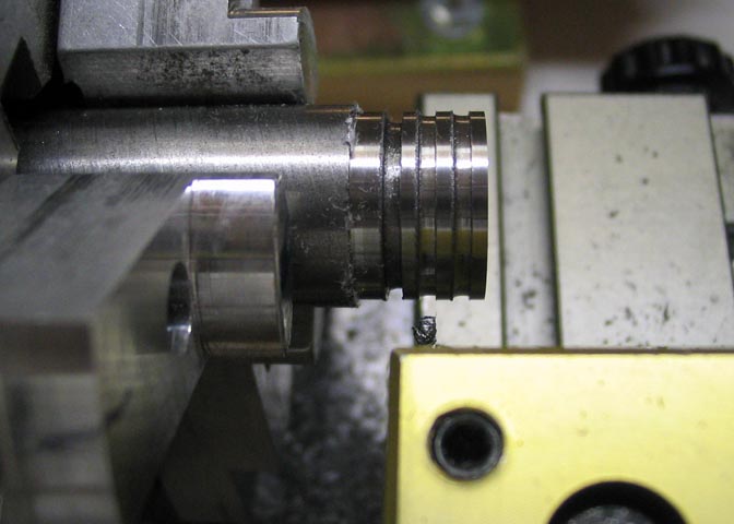
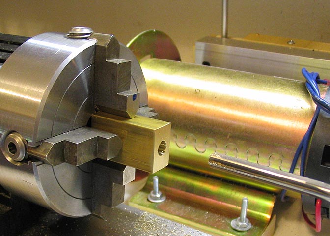
Now a knob is made for the end of the half nut shaft. I made mine .575"
diameter. No reason for that figure except it felt right. The grooves are .050" apart
and .075 deep. The groove nearest the chuck in this shot is where the knob
will be parted off once it is drilled and reamed for the 1/4" half nut shaft. A 4/40 hole
was tapped through to the bore in the center land for a set screw.
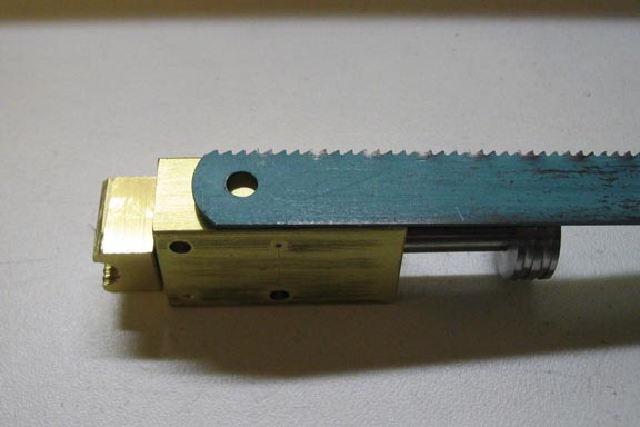
Now the block is removed from the carriage to make a friction spring for the half nut
shaft so it will stay where it's put. I used a worn out hack saw blade for this spring. I
save my old hack saw blades just for things like this. They are made of good steel
and can be re-hardened, but first...
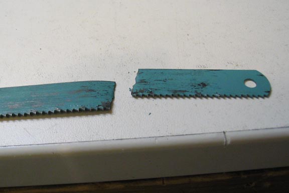
You have to anneal your blade. As they are, they will break if you try to bend them
sharply, like in the photo above.
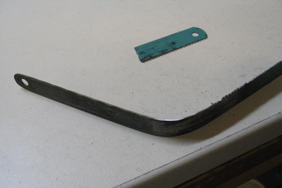
To anneal the hack saw blade, you can use a common propane torch. Heat the
portion you want to use to a dull red color and pull the torch away slowly as you
continue to heat the area you want softened. Keep pulling the torch away while
running it up and down the blade, until the flame is about 4-5 inches away from it.
The red color of the blade will fade as you do this, which is what you want. Once
you reach this point you can turn off the torch, and let the blade cool naturally. Don't
wave it around in the air to try to hasten the cooling. When it is cool enough to touch
you will be able to bend it at a 90 deg angle without breaking it.
You should do this outside your shop to avoid stinking up the place as the paint
burns off. If you need to do it inside, sand off the paint first. Sand lengthwise on
the blade. If you sand cross wise it will make marks that may crack when
you bend the blade to the shape of your spring.
Now you can grind off the blade's teeth and take off any sharp edges with a file.
Lay the piece along the bottom of the half nut mounting block and mark the block
for a 4/40 tapped hole. While you have the annealed piece against the block, mark
it with a magic marker where you want your bend. Don't scribe it or it will break when
you bend it. The point of the bend is not critical.
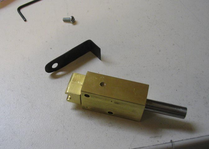
Bend the piece at your mark to 90 degrees and put the piece back in position on the
half nut mounting block and make another mark on the bent leg of the piece where you
will cut off the excess. You want to make your mark so the spring will have about 1/8"
of deflection when the piece is mounted to the block. The shaft for the half nut is
1/4" dia, so if you make your mark on the spring at a point that would be half way through
the shaft, you will be in the ball park. The measurement is not critical.
Now cut the excess off of the spring. Since it has been annealed, you can cut it with a
hack saw, just as if it were regular steel. Soften the edge of the spring that will run
against the half nut shaft with a file so it will not cut away the half nut shaft in use.
Once this is done, you can re-harden the piece. Heat it to a bright red. It's thin, so be
careful not to burn the metal. When you have your color, quickly dunk it in room temp
water. Polish it a little on one side, (lengthwise) with 600 grit to make it shiny so you
will be able to watch the temper come up. Then heat it again until it just starts to show
a blue-purple color, and quench again.
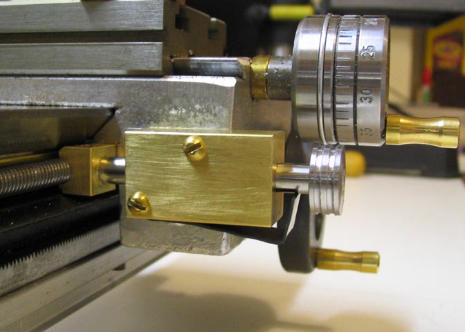
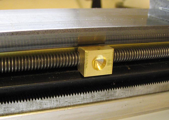
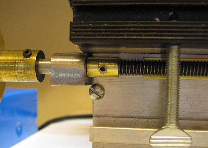
Here is the completed unit mounted to the carriage. The spring provides a good
amount of tension against the half nut shaft, and it will stay where you put it.
Now, for the lead screw. I turned off the threads of the LH rod for a length of
about 3/4", just until I had removed the remnants of the threads, and when I
drilled the holes in the end blocks, I used a bit that would give about a .002 larger
hole than the diameter of smooth area of the threaded rod where I had
turned off the threads. Then a small brass bushing was made that fit the end
of the shaft and will act as a bearing surface against the end blocks.
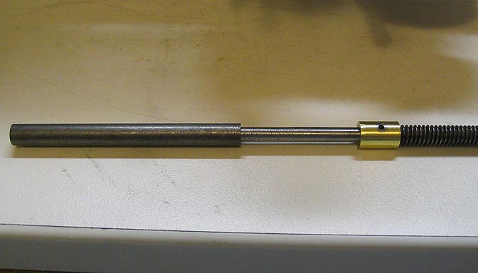
A similar job was done on the opposite end of the threaded rod, but the
part that has been cleaned of it's thread is much longer. About 2 1/2 inches
because this end will eventually take a gear for an upcoming addition of change
gears.
Since this end will need to be a little more stout, a piece of 1/4" shafting is
cut the appropriate length and drilled down it's center to match the diameter of the
end of the shaft. An adjustable brass bushing is put over the smaller diameter
of the shaft for the purpose of taking up back lash, then the bored shafting is
slipped over the end of the leadscrew and held fast with Threadlocker.
About 1/16" is left between the bushing and the shaft sleeve, to allow the
bushing to be moved as needed.
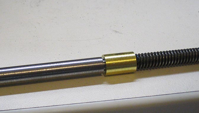
I used a set screw to hold the bushing fast. The bushing is very close to the lathe
bed extrusion, and the set screw needed to be filed flush with the bushing to
allow it to rotate.
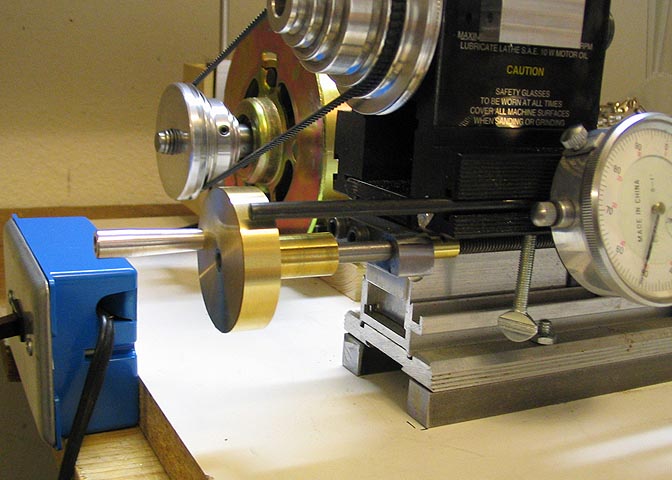
This is the finished headstock end. I didn't graduate the hand wheel, since I normally
use the dial indicator shown when advancing the cut. I left the shaft for this end of the
screw quite long, as I have a plexiglas enclosure for the lathe. I have a hole cut in the
end of the enclosure that fits over the leadscrew shaft so I can turn the hand wheel
with the enclosure in place. It saves a lot of stray swarf. As it stands, the leadscrew is
complete, and works very well. If you make sure to get everything lined up when
mounting the screw it will be very smooth in operation. Compared to the stock Taig
carriage rack and pinion advance, it is very easy to get a really nice finish on turning
jobs, but the rack is still fully functional for fast traverse by simply disengaging the half nut.
. There is more to come, though. I have a set of change gears all made up for
a threading project and there will be a few minor changes to this end when I get every-
thing machined for that assembly. That's another web page... Eventually.
More Taig lathe projects
deansphotographica.com
(home page)
Copyright Aug 2008, Dean Williams