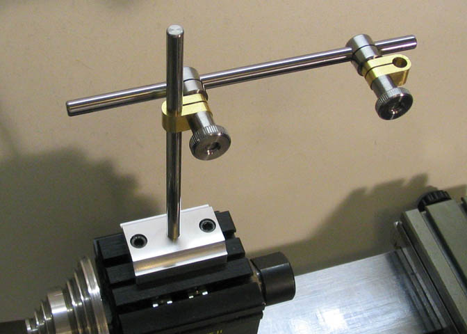
A Dial Indicator stand for the Taig lathe
After years of using an old surface gauge to hold my dial indicator I finally decided
to quit fiddling around and build an indicator stand. This stand mounts directly to the
Taig head stock, tail stock, or cross slide of the lathe, and can be used in the same manner
on the Taig milling machine head stock or milling table.
The fastening nuts were made first. They're turned from 5/8" steel round stock. The
smaller diameter is .375" for a length of .375". The larger diameter is a nominal 5/8", and is
skimmed to give it a nice finish.
The piece is then drilled through and tapped 1/4-20 for its entire length, which will be .6".
Tap well into the round stock to make sure you end up with threads all the way through
the nut.
Round off the corners with a file, then part the piece off at .6". Two of these are needed.
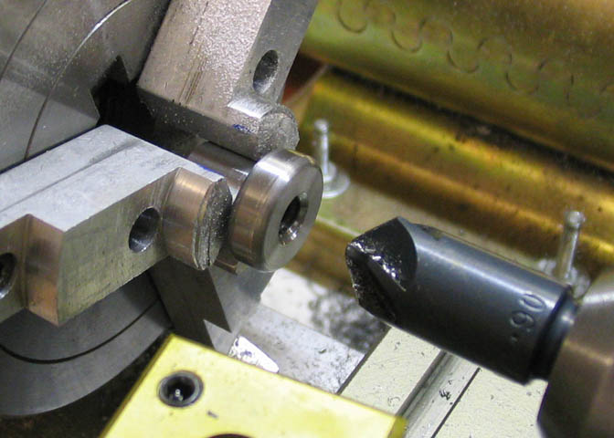
After the piece is parted off, a 90 degree counter sink is used to put a nice chamfer
in the ends of the threaded holes.
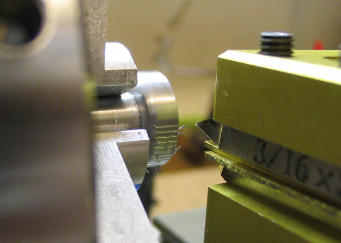
It would be best to knurl the two nuts, but I don't have a knurler, so I opted to cut a number
of grooves on the circumference of the knob part of the nut. I have a 60 hole index plate
mounted on the head stock pulley that makes this easy. The grooves are .005" deep and are
cut with a simple 60 degree pointed tool. The head stock is locked with the indexing pin and
the tool is fed into the work using the crank handle on the carriage.
There is a construction page for making an index plate for the Taig lathe on my main page.
See the link to it at the bottom of this page.
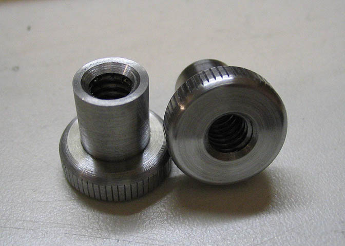
Here is a shot of the finished nuts.
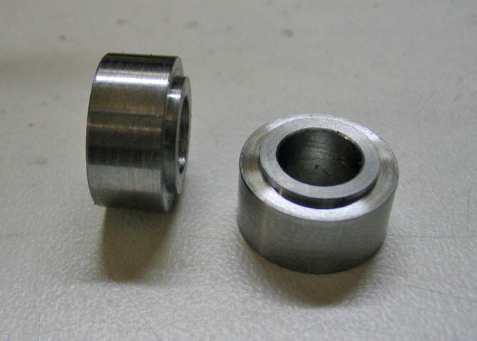
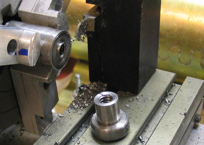
The next pieces, (two, again), are the thrust washers. Simple turning job, so just this one
pic should do. They are 1/2" diameter, total length of 1/4", and the smaller shoulder is 3/8"
diameter and .030" thick.
Next up are the two clamp shafts. Starting with 1/2" steel round stock, and a length of about
1 3/4", put them in the mill or drill press, and center the stock under the spindle. Drill and ream
1/4" holes in one end of each piece. The hole is located 5/16" from the end of the piece.
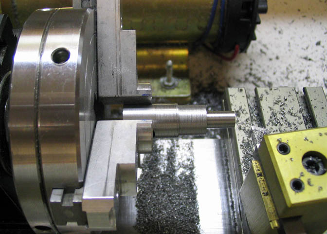
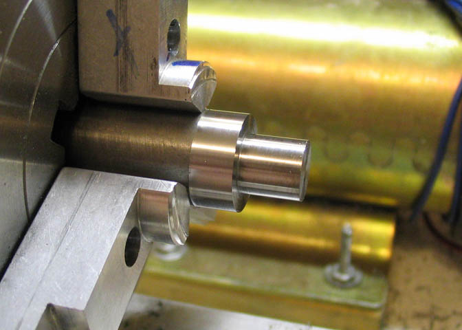
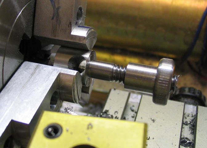
Put the end of the piece with the hole in the lathe chuck, and turn down to form a 1/4"
shaft, all the way to within about 1/10" of the hole in the other end. Since there is quite a
bit of material to remove on what will be a smallish shaft, cut the final diameter in steps to
provide extra support for the piece, as shown here. Doing it this way will minimize the
chance of the tool pushing the longer small diameter off center or pulling it out of the
chuck due to material flex.
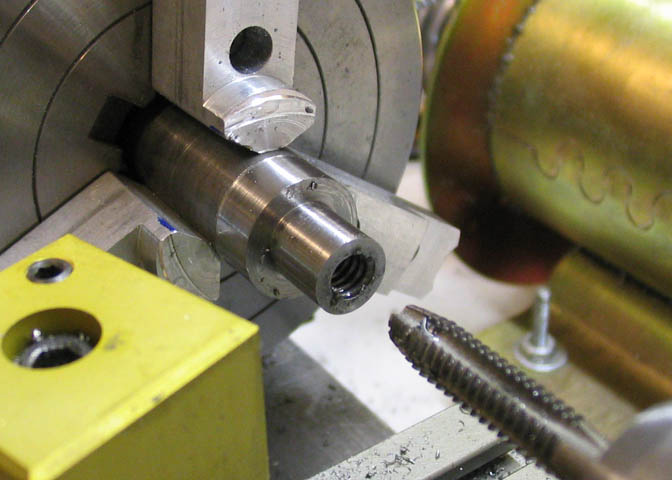
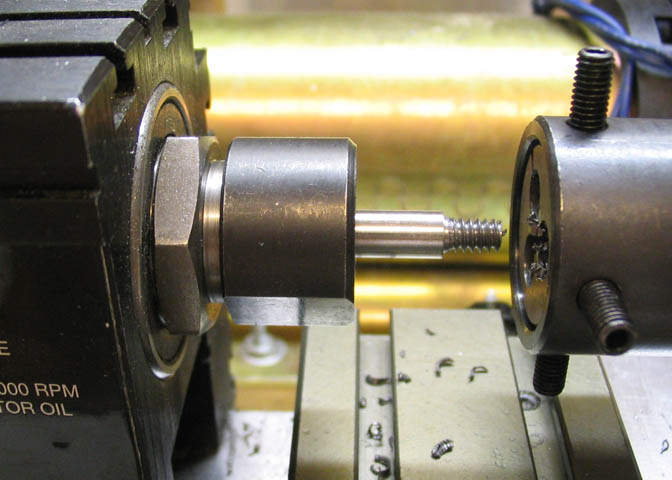
Keep whittling away at it until you get down to the final 1/4" diameter. There is still a small
portion of the shaft to be turned down, but before doing that the shaft needs to be threaded.
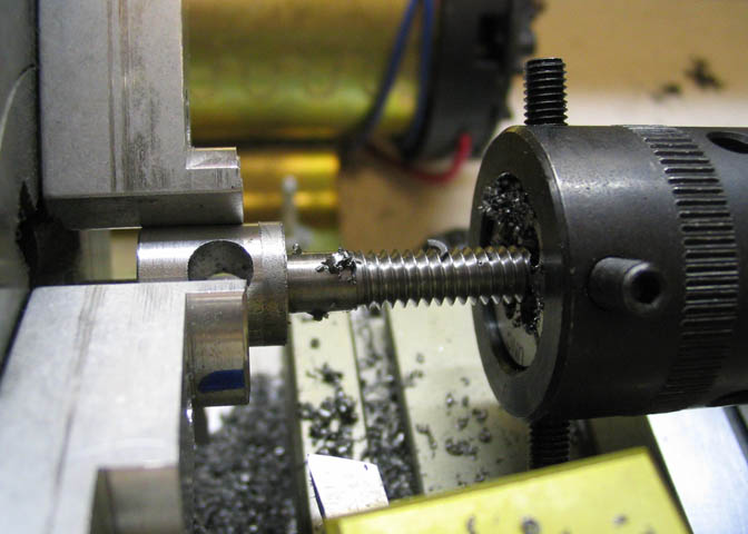
Thread it 1/4-20 for a length of 3/4".
When you are satisfied that the thread is good, the remaining bit of the shaft up to the point
that it meets the cross hole can be turned down. The last bit is left to provide the piece some
extra material to take the stress of threading.
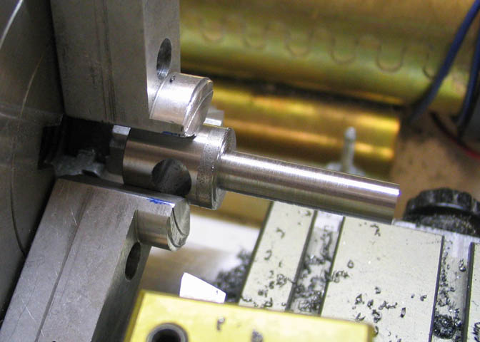
That last little bit turned down that meets the cross hole is turned right up to where it starts
to open up the side of the hole, then about .010-.015" more, until you have a gap in the side
of the hole that is just shy of 1/8" wide.
Be careful not to cut too deep. If you do, the end of the piece will just fall off...
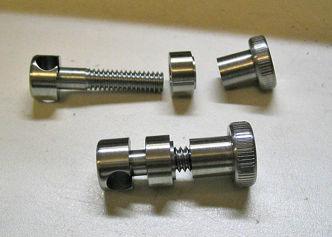
When all these pieces are done, they go together like this.
The two clamps are made of 3/8" square brass stock, and are 3/4" long. I started with pieces
a little over long so the ends could be cleaned up square, and also took a skim cut on the
sides to shine it up a little.
A hole is drilled and reamed for 1/4" on one end of each piece, centered, and .188" from
the end. Then the pieces are turned over and the same is done for the opposite ends.
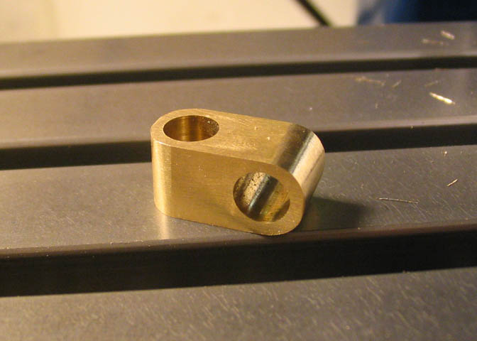
Once the pieces have been drilled and reamed the ends can be rounded as shown in the
shot above. A file will do this job in just a few minutes.
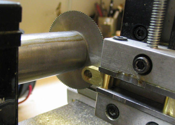
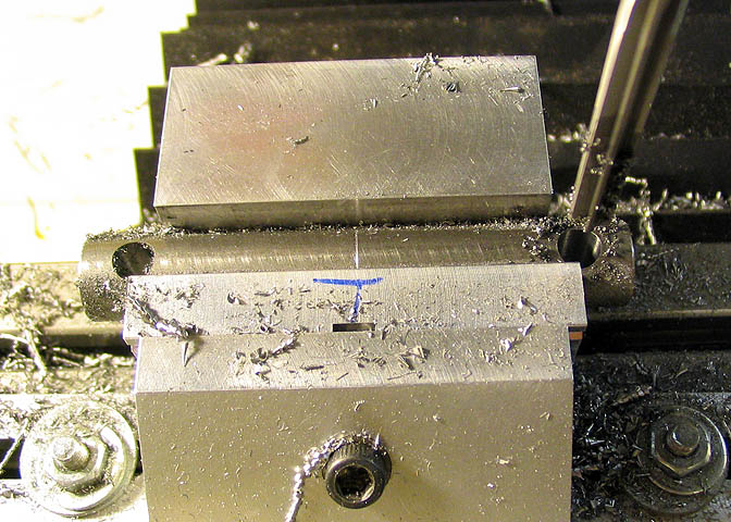
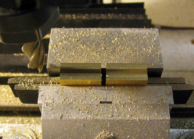
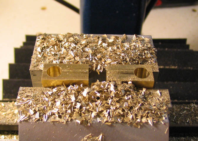
The piece is then put into a vise and a .032" slitting saw is used to slot the center of one end
of the the clamps. The slot goes just deep enough to cut through the wall of the hole in the
opposite end of the clamp.
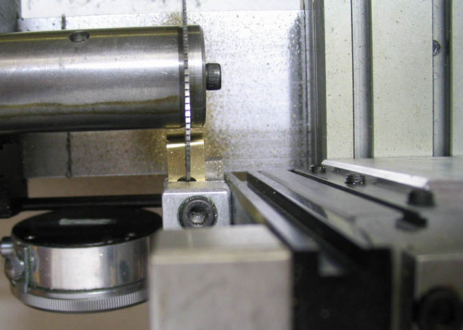
I used the milling attachment on the lathe to do this step since there was another setup
taking space on the milling machine. The shot above shows how the slot is cut into the
hole in the opposite end of the clamp.
(In this shot the piece appears to have been cut way off center, but it's a trick of the camera!)
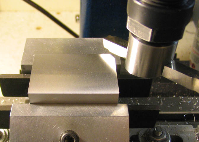
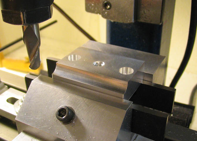
The base is made from aluminum plate. It's 1.750" long, 1.150" wide, and .5 thick. I used
a fly cutter to take a skim cut from all sides just to get rid of the dull mill finish.
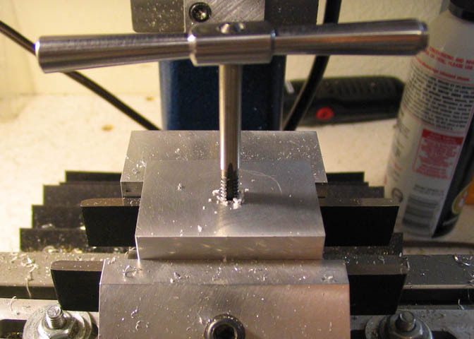
A hole is drilled in the center of the base and tapped for 10-24.
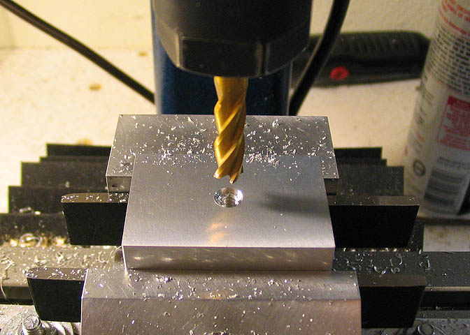
Then a 1/4" end mill is used to make a shallow counter bore to a depth of .070"
Clearance holes for #10 screws are drilled on the center line of the base, .650" on either
side of the center line of the threaded hole. After drilling, counter bore for a #10 socket
head cap screw.
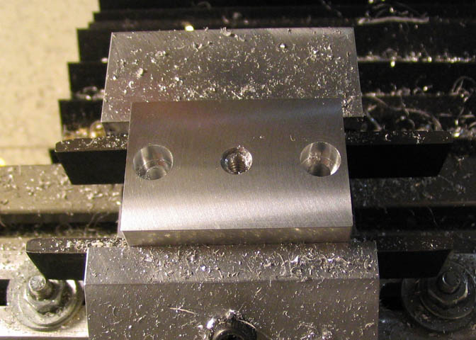
The last step on the base is just for a little dress up. Something to break the corners on the
long edge makes it look less "chunky". I used a 3/8" ball end mill, found the top and side
surfaces, and milled 3/16" down and 3/16" into the side.
For the main post that threads into the base, 1/4" drill rod is used. The end is turned down
and threaded for 10-24 for a length of .300". The last bit of thread where the threaded
portion meets the main part of the rod will not quite thread into the base, since the die cannot
cut a thread right up into a corner. So, that last little bit is just cut out using a parting tool.
This is the last step in this construction. Thread this post into the base and assemble the rest
of the parts as shown in the first picture at the top of this page.
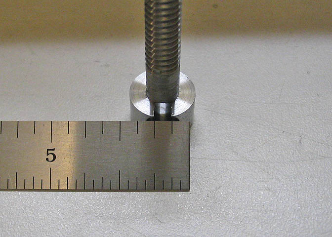
Note: The length of the post that goes into the stand is 5". The longer cross piece shown
in the pictures of the finished stand can be made to what ever length is convenient. I made
mine 6", which seems to be about right for my use.
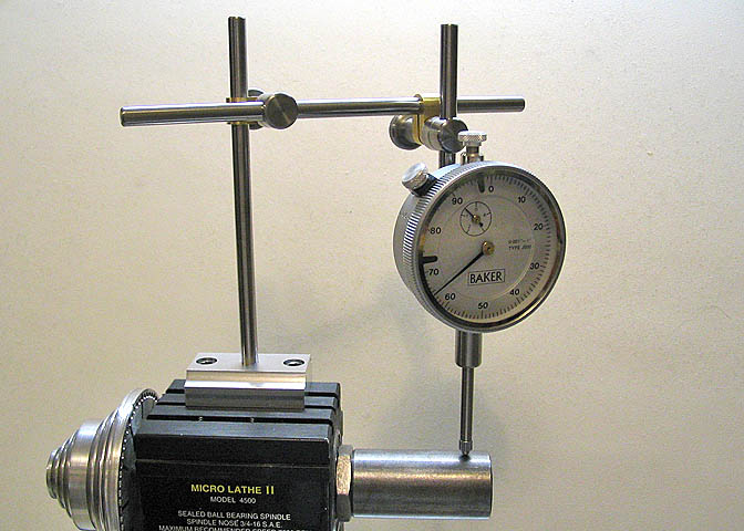
Here's the new stand in use.
More Taig Lathe & Mill Projects
deansphotographica.com
(home page)
Copyright Dean Williams