An Auxiliary Spindle for the Small Lathe
(See the update on this spindle near the bottom of the page)
I made this auxiliary spindle for my Taig lathe as a means of completing another project I had started.
As it often happens, before you can make one tool, you need to build two or three others to allow you
to finish the original job. The original project needs holes drilled precisely around the axis of a work-
piece mounted to the lathe spindle. An auxiliary spindle that mounts to the lathe cross-slide will do it.
You can see the finished spindle by scrolling to the bottom of this page,
or you can start here at the top and see how it all came together.
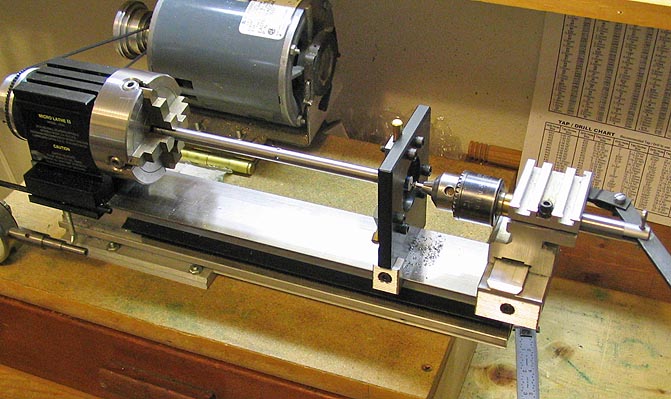
Probably, the cleanest way to make the body of the spindle would be to mill it from a solid block of aluminum.
I didn't have a large enough piece for that, so I went with a built-up unit.
Here, the base has been laid out and drilled for Taig T slots, bolted to the cross slide, and the ends are
being cut square with a slitting saw.
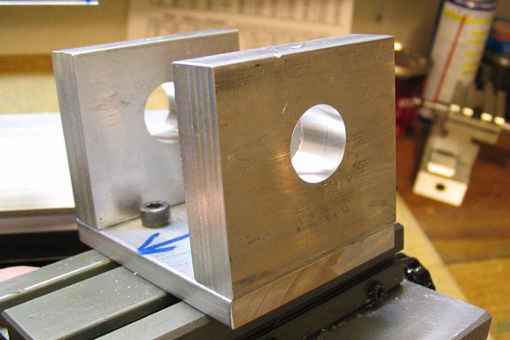
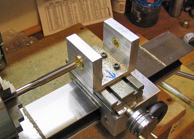
The sides, or uprights for the body are milled square.
Holes are laid out for mounting the uprights to the base plate, drilled, and tapped. The socket
head screws are countersunk. I used 1/4 x 2" aluminum for the base and 1/2 x 2" for the
uprights. I had to face off the heads of the socket screws to allow them to mount flush with the base.

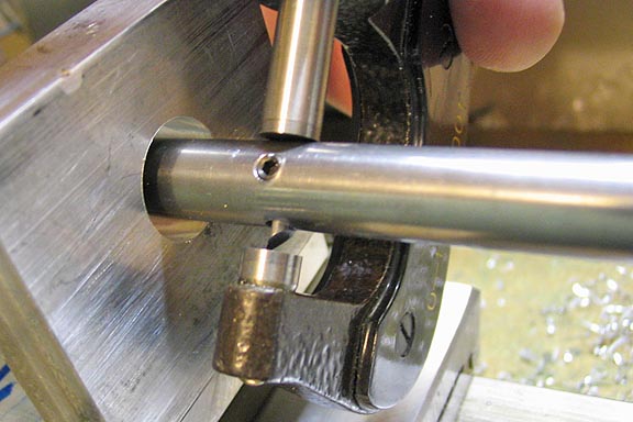
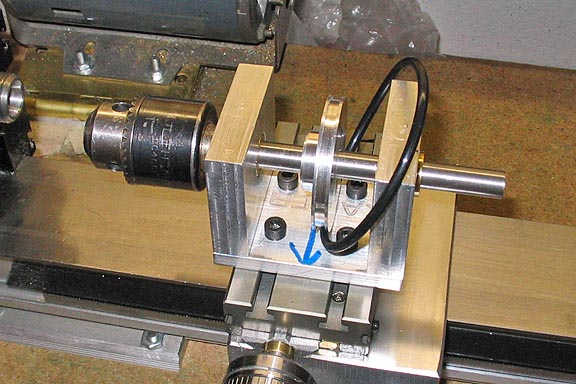
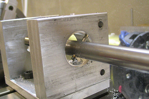
The assembly is mounted square on the cross slide, and the center point of the uprights drilled through.
The drilled hole is just a starting point for boring.
I found the center by horizontal coordinate, using the edge of the upright to find center. For finding the edge
of the upright, I used a method taught me by an old machine head. A center drill is mounted in the chuck,
the saddle racked over so the near edge of the upright on the left side in the pic is on the far side of the
center drill. Then a cigarette paper is held between the center drill and edge of the upright while you spin the chuck.
The cross slide is cranked back until the cigarette paper is pulled or torn by the
spinning center drill, as it is pinched between the drill and edge of the upright. At that point, you will be within
about .001" of the edge. From there you can use the reading on your cross slide dial to find center. Take half the
width of the center drill, plus half the width of the upright, crank that figure in with your cross slide dial, and
you have your center.
By the way, I don't smoke. I buy Zig-Zag cigarette papers at the market and keep them in the shop for this.
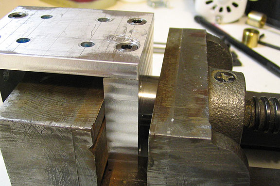
Since I want the bore through the body to be pretty true, I'll align bore it. This is also called
line boring, and that is probably the more common term.
This brings up another tool that needs to be made. (A tool, to make a tool, to make a tool, and etc...)
The only boring rod I had for this purpose was a great big one left from a time when I had
a much larger lathe. I have to make a small one, suitable to the Taig lathe.
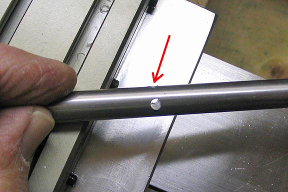
I cut a piece of 3/8" drill rod to an appropriate length and drilled a hole in a position that would let
the body of the spindle pass over the hole, without running into the lathe chuck, or the tail stock.
Also, a single hole was drilled and tapped for the set screw to hold the cutter.
The bar is indicated true in the 4-jaw chuck, and the steady rest is run up close to the chuck and set. Then
the steady rest is run back down to the end of the rod and clamped down. A center drill is used to drill a
hole for the center, which will hold the bar true during boring.
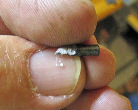
The cutter for the boring bar is made from 1/8" W-1 drill rod. The cutting edge
is ground while the cutter blank is un-hardened, then the cutter is hardened by
heating it to a bright red with a torch, and quickly quenching it in water. The
cutter is then polished with 600 grit paper, and tempered to a yellow or straw
color and quenched again. Scraping it lightly against my thumbnail shows
the cutter to be sharp enough for the job. The final step is a light honing.
Then it's inserted into the hole in the bar and tightened down.
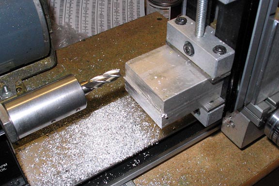
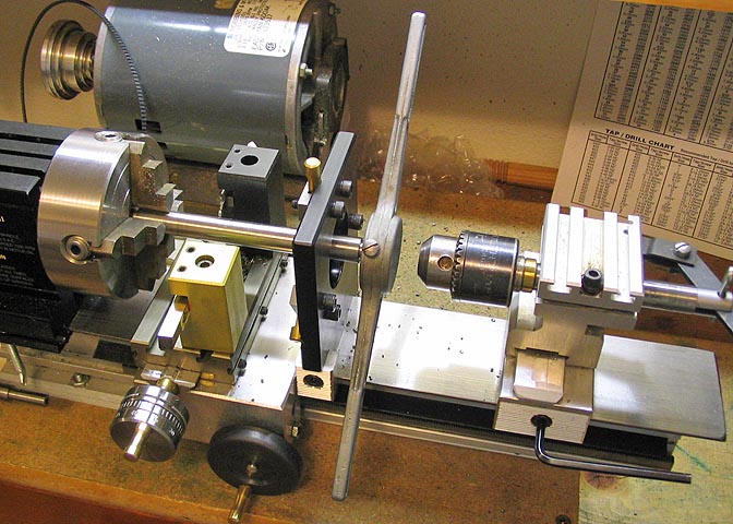
Here's the boring set-up ready to work. I'm using a live center in the tail stock. The Taig live center has
a spring loaded center that must be pushed tight against the work piece. The cutter is not visible in this
shot, but it is at about the center of the boring bar. A position that lets both sides of the spindle body pass
over it without hitting the chuck or the tail stock.
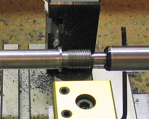
This is the first cut. Even though the boring bar is only 3/8" diameter, while being about
10" long, it can take a fairly good cut. When nearing the final diameter, the cut should be
quite light for this size bar, though, to prevent flexing. About .002" for the final cut, and the
bore should be true.
To measure for the last few cuts, a mic will do well. After measuring the bore to find how
much more of a cut is needed, loosen the cutter and extend it half that amount. I measure
the current setting of the cutter and mark it down before adjusting, just so I don't loose my
place when I loosen the cutter screw. It can take a minute or two to get the cutter set just so.
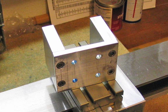
The completed bore job. The Taig carriage comes off the lathe easily for measurements
of the bore. The cross slide setting must not be disturbed though, and needs to be locked
with the gib.
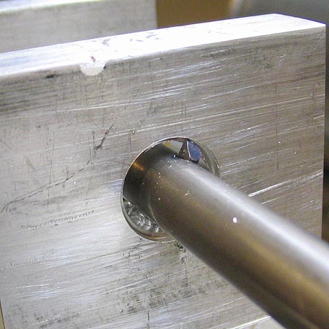
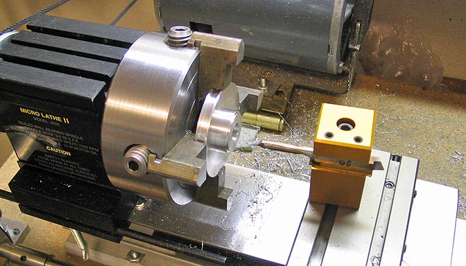
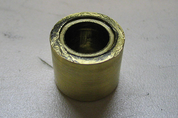
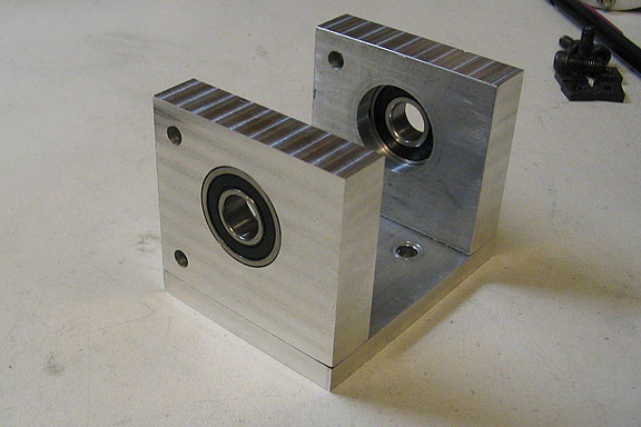
This bore is made to correspond to the size bearing I had a mind to cut.
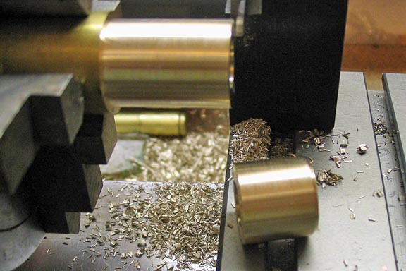
The bearing is of plain brass. The center hole is bored to within a few thou of the reamer I
intend to use, and cleaned up with the reamer later. The outer diameter is turned to a scant
.001 over the size of the bore in the body, for a snug press fit.
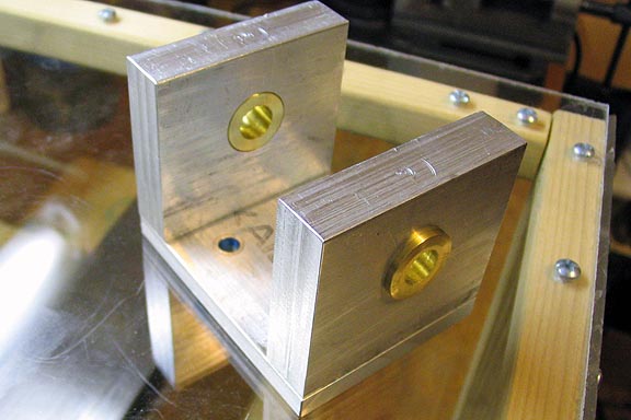
The bearings are started in their bore holes with a drill press, and then pressed home with
a large mill vise or arbor press. I left the outside of the bearings about .050 proud of the out-
side surface of the uprights of the body to provide a thrust surface for the spindle. The
insides are flush.
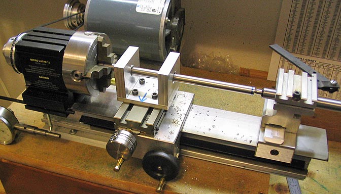
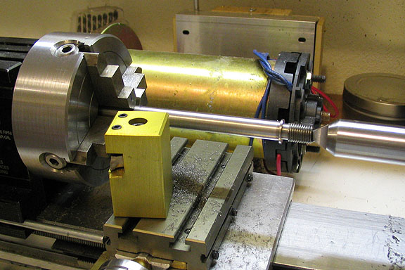
The body is once again mounted squared and mounted to the cross slide, and the center indicated
in by coordinate, as I did for the initial boring of the uprights in the beginning. Then the bearings are reamed
for the spindle. I used a 3/8 ream for this step.
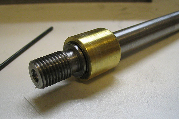
For the spindle, I used a piece of 1/2" CRS. The end is turned down and threaded for 3/8-24.
A landing is turned behind the threads so a drill chuck or tool arbor can mount flush
and true. Behind the landing, a short bit of the original diameter is left to act as a
thrust surface to ride against the bearing face. Then the remaining diameter is turned
to the proper dia, and polished with fine crocus cloth or 1200 wet/dry paper.
After the threads are cut, all remaining work on this piece is done between centers.
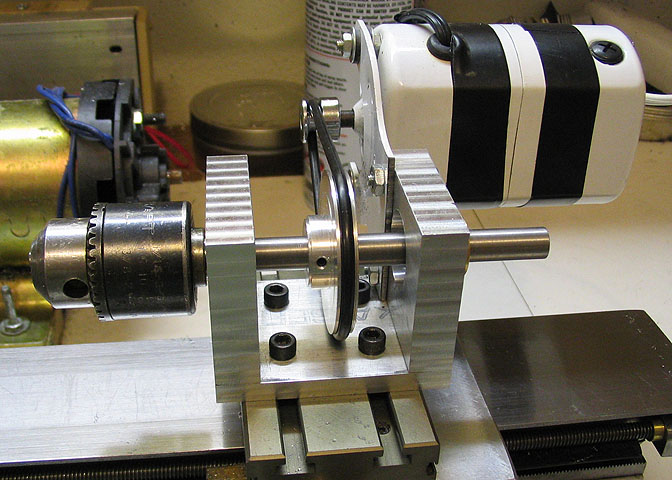
I turned a pulley of aluminum and bored it for the arbor. Then it was drilled and tapped for a set screw.
I made this as large as would fit in the spindle body, since I am going to use a sewing machine
motor for power, and need all the reduction I can get.
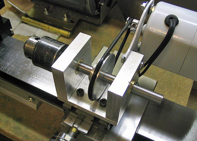
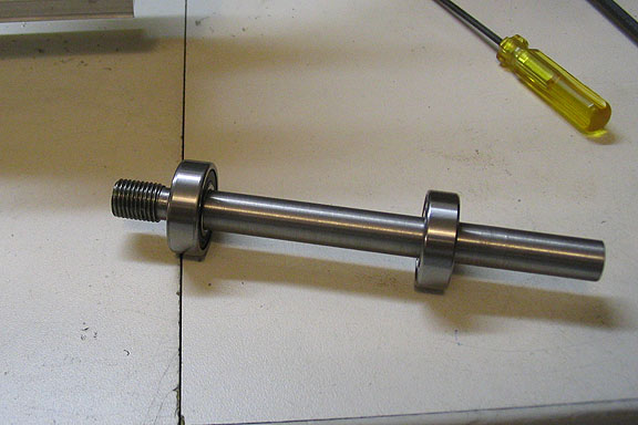
The fit-up of all parts, shown with the O-ring drive "belt". Past experience has shown
O-rings to be very tough when used as a drive component. They do stretch though.
Belting for a watchmakers lathe will work better, but for the little power provided by the
sewing machine motor I'm using, this will do well.
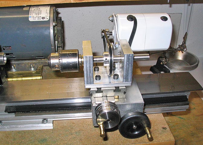
This the the finished item, shown with the run-of-the-mill $15 replacement motor for a sewing machine.
Another view. Since all thrust should be from the front end, that is, the drill chuck end, I didn't equip this
with any kind of thrust for the back end of the shaft. If I find it wants to run in and out of the bore in the case
of drilling a hole and sticking the drill bit with cuttings, I'll just make a simple steel collar for the back end of
the shaft. I left the shaft long at the back in case I should need to mount the pulley in that position sometime.
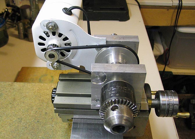
The business end, where you can see my goofs on the left side of the drill chuck. I had drilled the mounting
holes for the motor there. After hooking up everything, I realized I had put the motor on the wrong end!
It ran backwards. Live and learn. After drilling new holes in the other end and rotating the motor 180 deg.
everything is going my way.
Now I can continue with the original project. The one I was working on when I found I needed to start this project.
It never ends.
An update on the auxiliary spindle.
After about a year of use, and an awful lot of holes drilled, the brass bearing on the front
of the spindle gave up the ghost. The brass just wasn't up to the task, but if I had used
a thrust washer, it probably would have lasted longer. It's okay. I got a lot of use out of
it using the brass bearings. All that was required to get it going again was a set of sealed
bearings from the local auto parts store.
The spindle got pretty tight in the bearing, and I had to drive it off the shaft.
The back of the chuck mating surface of the shaft has gouged out a groove in the bearing
where it ran against it.
The new bearings I bought were listed as .375" bore in the parts book at the auto supply
store, but two dial calipers, a telescoping bore gauge, and a micrometer said the bore was
actually .374, so the shaft wouldn't fit in the bearings. The shaft is indicated in to run "0" all
around, and a slim whisker of a cut is taken to bring the shaft down to .3735". A nice
close fit in the new bearings.
The shaft is checked for fit in the new bearings.
Since the new bearings are larger in diameter than the old ones, the main spindle body needs
to be rebored. The same method is used as when the piece was first made. A new cutter had
to be made too, since the old one was too short to make a large enough bore. The cutter is
made from an old broken drill bit. I save all my broken bits and dull end mills for making cutters.
Now the new bearings are pressed into place with a vise. The interference between the bore
and the bearing race is just under .001", and a vise will press them together pretty easily.
The main body with its' brand new bearings. The bearings are KYK brand #R6-2RS.
And it's back in action. New bearings and a freshly milled exterior, just for looks.
More lathe projects for the Taig
deansphotographica.com
Homepage
Copyright 7-08 Dean Williams