The Craftsman 109 Lathe Rebuild Project
Here's where the project begins, with the lathe as I received it.
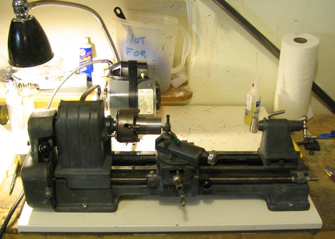
Typical blue/gray color that's probably been recoated a time or two. At this point, all I've
done to it is take off the main bits for cleaning. Head and tail stock, gears, carriage,
and like that. Then put it back together and adjusted the gibs best I could and made a
test cut. I used a piece of stock that's a little large, but since I know my Taig lathe
will put a mirror finish on a piece like this, it's a good bench mark, (if a little unfair to the
old Craftsman).
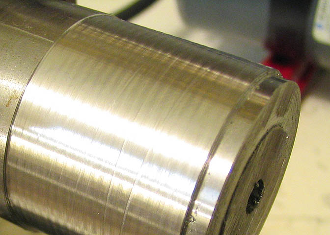
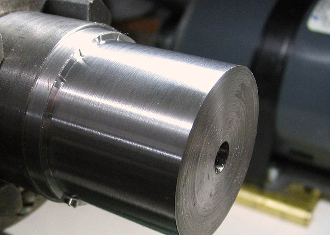
This is the best it would do, which is pretty awful, really. These scallops are easily felt as
dips in the surface when I run my finger across them. This is caused by a combination of
maladies in the old lathe. Partly by the poor gibs, partly by the very worn rear bearing, and
some from the somewhat worn front bearing.
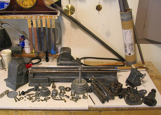
The lathe was completely stripped down for a through cleaning and some much needed new
paint.
The first piece made in the way of improvement is a new rear gib. The stock gib is made of a
crude chunk of cast iron with but a small bearing surface of only about one inch long. This
gib will extend over the entire width of the rear of the carriage bearing surface, which will
help distribute the cutting forces produced by the lathe more evenly over the ways.
Basically, the gib is made to the same shape as the original, with the exception of the longer bearing surface.
Finished rear carriage gib.
The carriage is put into the drill press and a couple of holes drilled for 6-32.
And the new gib is mounted like so.
At this point, the lathe was re-assembled and another test cut made. Still pretty rough, but
what a difference from the first cut! Almost like a lathe did it.
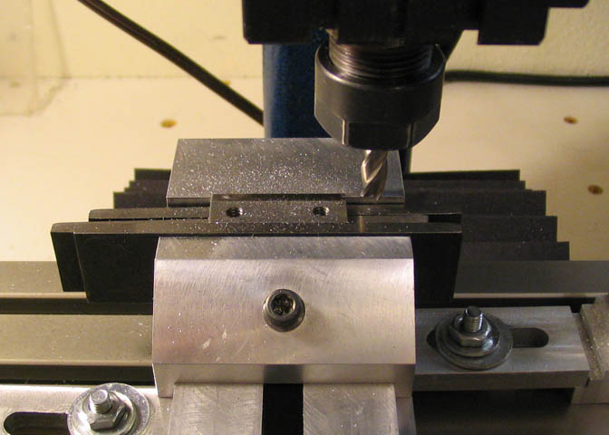
I put the "gibs" from the front of the carriage in the milling machine and took a skim cut
where the metal plate runs against the underside of the front lathe ways. This thing is not
really a gib, but I don't know what it's properly called. There are two of them under the
front of the carriage, and ideally, they would be part of the carriage itself, like on other lathes.
They were pretty rough, and they are made for some adjustment, so a light cut to smooth them
should help with friction, if nothing else.
The cross slide has only two gib screws, and they are at the very end of the gib "V's".
This means when you draw the cross slide all the way back, the gib screw nearest the
operator is pushing on nothing, since the rear of the gib comes out of the gib channel.
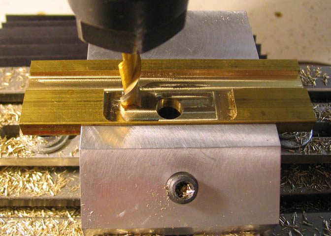
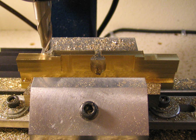
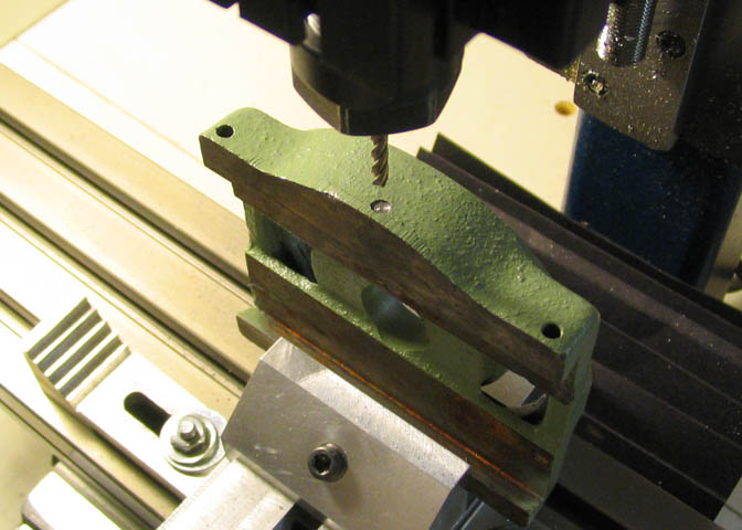
Here a flat is being milled to locate a third tapped hole in the cross slide table that will
provide more equal pressure on the gib for its' full length of travel. There is a little casting
flash at the point where the threads need to go, so the milling step shown here. If a milling
machine is not available, a flat can be filed into the casting.
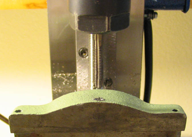
After the flat is milled, drill and tap for 8-32 all the way through into the gib channel.
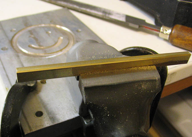
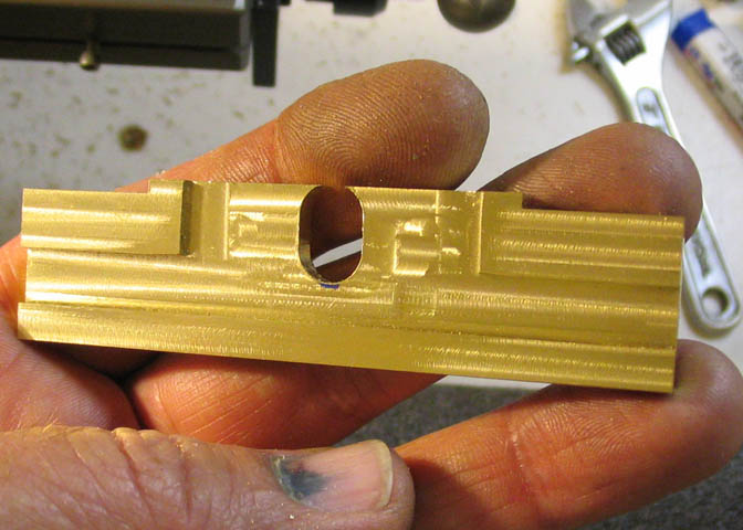
As long as I'm working on gibs, I made new ones for the cross slide and the compound slide.
They are the same except for the length. They are .25" wide and .125" thick. The cross
slide gib is 3.535" long and the compound slide 4.150" long. The originals are steel, but steel
against the iron of the slides doesn't make for smooth sliding the way that brass will, so the
new gibs were made of brass. These were milled from some .125" thick plate, but common
1/4" x 1/8" brass stock will make for a faster job.
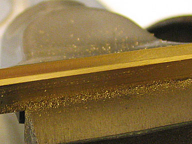
The gibs need to have two bevels filed or milled on opposing corners. The bevels do not bear on anything,
but just allow the gib to slide into place without the corners of the gib rubbing on the cross slide mating surfaces.
File or mill them at approximately 45 degrees, and make the flat 3/32" wide and it will be fine.
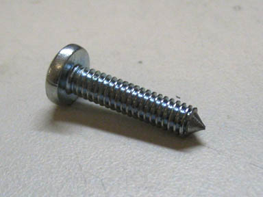
The screw for the new threaded hole in the cross slide is a common 8-32 pan head
that has had a point turned on the end that will catch in the gib material the same as the stock screws.
Before installing the new gibs, polish the wide side that will bear against the gib channels in the
cross and compound slides. The side that sits against the adjusting screws does not need to be
polished. For polishing, a piece of 1200 wet or dry paper can be placed on a piece of glass or
other flat surface, and the gib rubbed back and forth on it long ways. It will only take 10-20
strokes and the gib will be nice and shiny smooth. It'll make a difference!
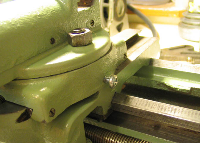
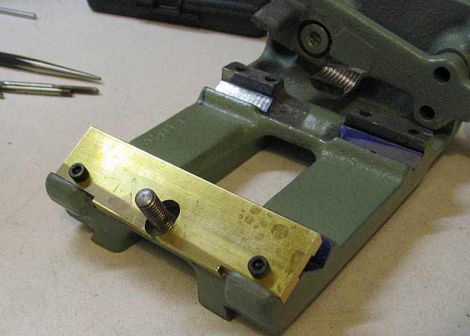
The new gib screw is shown here in the center of the picture. This screw not only provides
for better adjustment of the gib, but allows easy locking of the cross slide by tightening it.
You can see in the lower left of the picture where the back of the gib is about to come off
the gib channel. The cross slide still has quite a bit of rearward travel, and when cranked all
the way back, the end of the gib and it's screw are just hanging out in the air, doing no good.
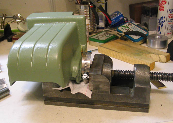
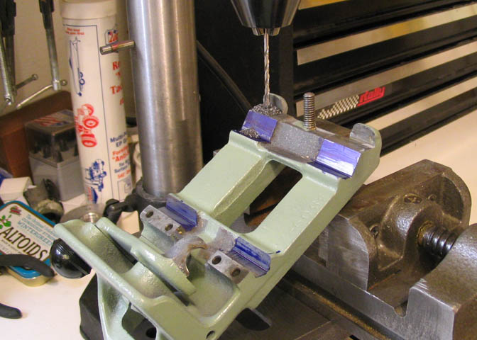
The next step was to press out the rear head stock bearing. The front bearing is tapered, and
comes out easily by removing the bearing pre-load nut. The rear bearing has to be pressed
out. Not having an arbor press, I just used a drill press vise. There is a brass slug against the
left jaw on the vise and resting against the bearing. The hose clamp in the picture is just to
provide space for the bearing to push into as the vise is screwed shut. A pipe nipple would
have been a better tool, but I didn't have one handy.
Care has to be take with this step. The head stock is cast iron, and therefore somewhat brittle.
It needs to be firmly supported to avoid cracking it, and tension cannot be put on both sides
at once or it will break.
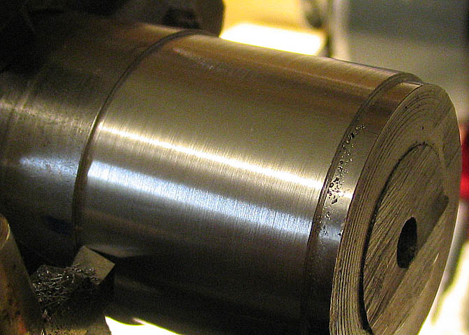
The outer, or rear bearing showed visible play when putting hand pressure on the spindle.
When I got it out and measured it carefully, the bore showed .555", which is way too much.
Just plain worn out.
The stock for the rear bearing is common Oilite available at good auto parts stores. There is
no standard size made for the bore of the lathe spindle, which is .550", but there is a stock
size with a 1/2" bore, which can be turned to size. The size to buy is 3/4" OD by 1/2" ID,
one inch long.
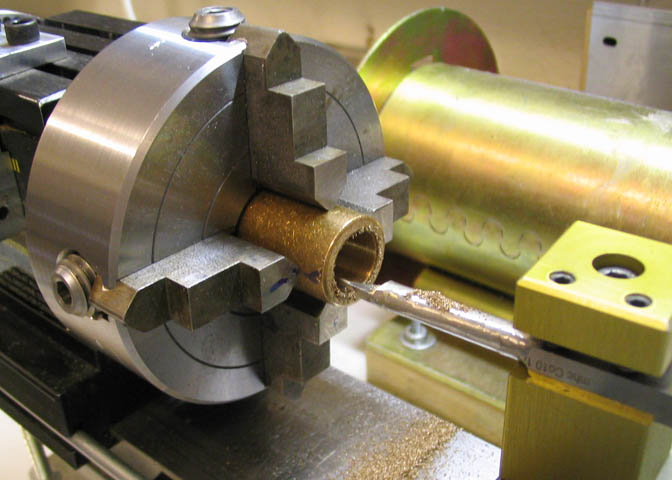
The bore needs to be just big enough for the spindle to fit without any slop, which is about
.5505". When chucking the piece it needs to be dialed in carefully to keep the bore concentric
with the OD. It flexes a little, so don't use a lot of muscle when chucking it.
The OD that comes as the stock size is about .753", which is a really tight fit in the head
stock bore. Really tight. Once the ID is turned for the spindle, the bearing can be finished
down a little with a file in the lathe. Let it hang out of the chuck jaws a little over half its'
length and run the lathe slow and finish the OD down to about .751". It will still be plenty
tight in the head stock bore.
For the inner head stock bearing, I ordered one from Bill Harden. It is a good lathe project
that can be made in the shop, but Bill had them in stock, so...
Check out Bill's web site for parts. (He prefers phone calls. Number is on the site.)
Home Shop Supply
After the above repairs and adjustments, I took another cut. This was before I received the
new inner head stock bearing. Getting better all the time. Still looking for a little better though.
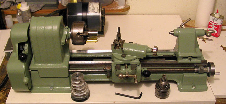
Here's a shot of the lathe with the new paint. I'm probably the only guy in Idaho who has a
lathe painted in desert sage.
Back to Craftsman 109 Projects
More Taig Lathe & Mill Projects
deansphotographica.com
(home page)
Copyright Dean Williams