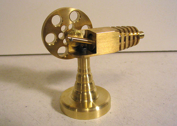
Building a "Rocker" Engine
This little engine project is just for fun, and a great little project for the
hobby machine shop. The engine runs on air, and doesn't really "do" anything,
but it's fun to watch. You'll be surprised how many grown men will just stand
around a look at a tiny running engine.
I've built quite a number of engines in my small shop. Some fairly complex, and
some that are a fairly simple. This engine falls into the later category, and is a
fairly good starting point for the beginning machinist who wants to delve into the
world of small engine building without having to tool up for complex parts like are
needed for some steam engines, and most any internal combustion engine. There
are less than 10 parts to be made, and with a little care the novice can have a running
engine for the work of a few spare evenings, or a weekend.
The engine shown here was built during the morning of one day, and the evening
of the next. About 10 hours from start to finish.
You can do all the operations for this engine with only a small lathe that has a
milling attachment, though I used both lathe and a milling machine. Other tools
that are needed will be pointed out in the text.
Materials are minimal. A couple of inches of 1/2 x 1/2" square brass, a couple inches
of 3/8" brass rod, and a couple screws for the main engine. That will take care of the
engine part. One more piece of brass (about 2 1/2 to 3" in length) 1 1/4" in dia will
get the base and flywheel done.
The prints for this engine are at this pdf link:
Rocker Engine
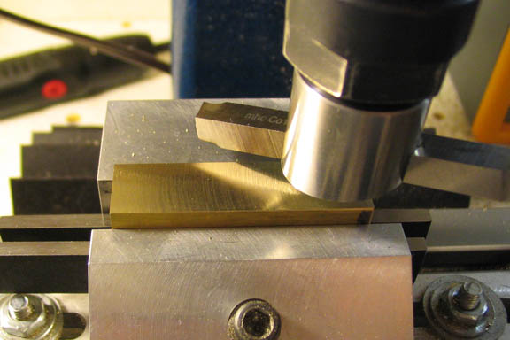
The first piece I worked on was the cylinder. It can be made from 1/2" square
brass stock just the way it comes from the supplier. I chose to take a light fly cut
off each side to clean up the finish a bit. The piece seen here is somewhat longer
than what is called for in the print, but that is only so I can add my own touches
to it later.
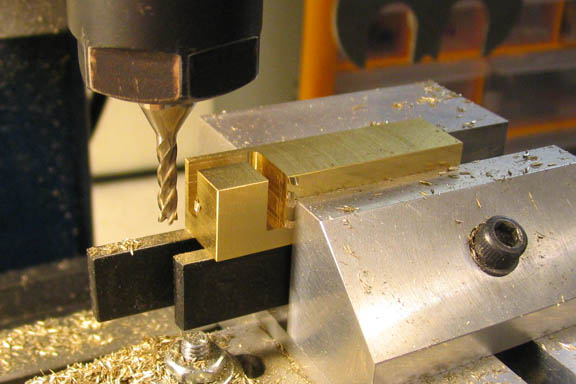
Follow the print for the cut-away part on the open end of the cylinder. This is a
small enough piece to be milled in a milling attachment on the lathe. If you have
a milling machine, it just makes it a little easier.
When the end has been milled out, drill the two holes called for in the print. The
larger of these two holes needs to be located carefully as it determines the location
of the crank shaft and its bearing.
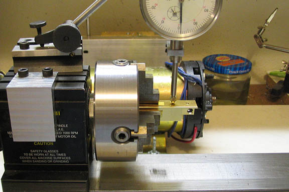
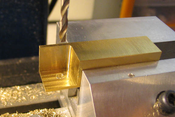
When the milling and drilling on the piece has been finished it can be indicated
in on the four jaw chuck. If you don't have a four jaw chuck, the piece can be
carefully mounted in the lathe's milling attachment for the next steps.
The piece is then drilled to near finished size and then bored the final few thousandths
to get a nice smooth finish. If the piece needs to be mounted in the milling attachment
to do this step, then it will probably be easier to ream this hole for the final finish.
Either way will work fine.
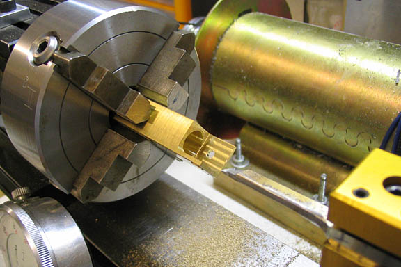
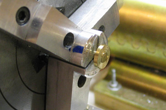
This is the reason I left the piece longer than the print specifies. I just wanted
to make it look a little different than a basic square block. What I'm going for
here is kind of the look of a "stinger". I guess I'd call it a Bee's Butt.
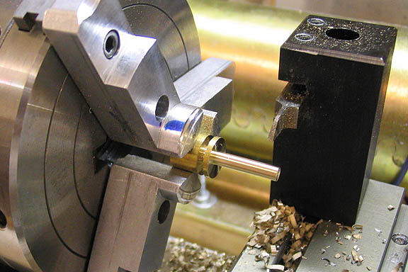
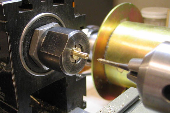
As can be seen in the shot above, a number of slots have been cut with the
parting tool, and each slot to the right is a little deeper than the one to its left.
The very end is turned down so it will fit a common size of tubing, which is
3/16" in this case. A small hole (about 3/32") is then drilled completely through
to allow air to flow into the cylinder.
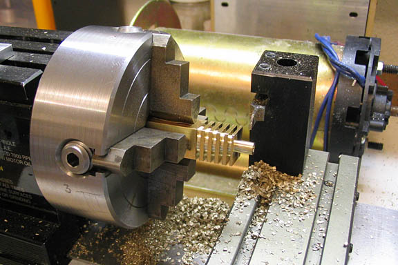
When the slots are all cut, the compound slide is set to an angle similar to the
one created by the slots, which form a kind of taper, since the slots get deeper
as they go toward the right end.
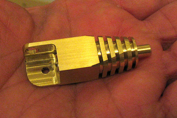
See, kind of like the business end of a bee.
A Bee's Butt.
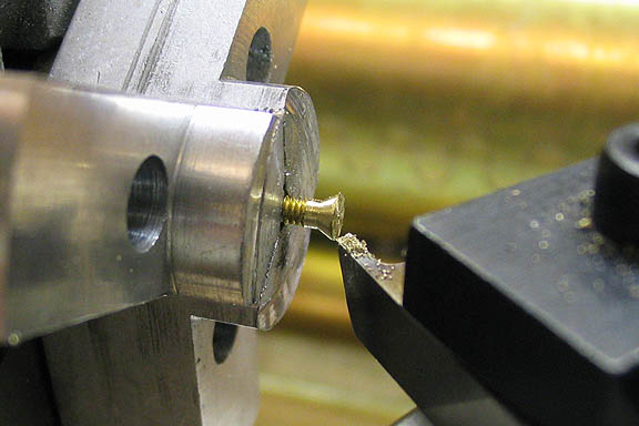
I didn't have a 2-56 flat head screw as called for in the print, so I made one from
a 2-56 cap screw. Here the taper is being cut beneath the head of the screw.
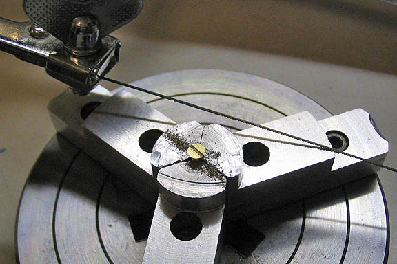
And then the screw slot is cut with a jewelers saw.
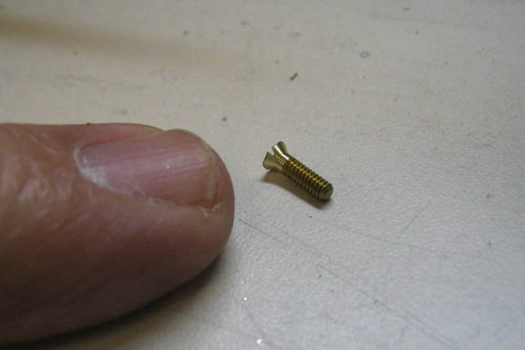
Many hobby shops that carry RC and model railroad supplies will have a
supply of tiny screws, and that would be the place to check for the screws
needed for this project.
The piston is made from a piece of 3/8" diameter brass. A simple turning job.
Turn down the shaft to length, and then part off the big end so it leaves about
1/16" on the end to clean up in the next step.
Then mount it in the chuck and face it off to length. This step has to be done
carefully, since the big end of the piston is only .020" thick. When the right
thickness is reached, check it for fit in the cylinder. Return it to the chuck and
use a fine file as needed to bring it to a close slip fit. Bevel the edges carefully
with fine sand paper taped to a popsicle stick.
The last step on the piston is to drill the crank pin hole. Take your time and
get the hole in the center of the shaft.
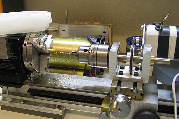
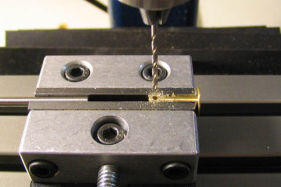
I didn't take enough pics of the crank disc, but it's another simple turning job.
Face off a piece of 3/8" diameter brass rod, drill and counter sink the end as shown
in the print, and drill the crank pin hole. In the shot above, the crank pin hole is
being drilled with an auxiliary drilling spindle mounted on the cross slide. Not every
hobby machinist will have one of those, but you can also do this step after parting
off the crank disc. Mark it out carefully, center punch the location of the hole, and
drill it in a drill press, or even using a hand drill if that's all that is available. Take
care to get the hole straight.
The crank pin that goes into this piece is just a piece of 1/16" diameter steel rod.
It's not mentioned in the prints, but it needs to be about 1/4" long. Clean up the
ends of it with a file or sand paper and it's done.
The crankshaft, or axle, is another regular turning job. If you start with 1/4" dia
brass rod, all that will be needed is to turn down both ends and drill and tap it.
It's probably best to turn down the plain (short) end first, so it can then be held in a
chuck or collet and then the other, (longer) end turned and drilled for a 2/56 tap.
If the tapped were turned and tapped first, when it is reversed in the chuck, the
chuck jaws could possibly put enough pressure on the hollow end of the shaft to
deform the shaft, making it difficult or impossible to screw in the flat head screw
that holds the crank disc to the shaft.
One more piece to make for the main engine unit is the crank bearing. I didn't
think pictures of that part were necessary, since its just a piece of 3/16" dia
brass rod drilled through and reamed.
One thing I would note about the crankshaft and the crank bearing. The print
shows the bearing having a .126" hole bored through it, and the threaded end
of the shaft having a diameter of .125". That will fit fine, but it will be easier,
especially for the beginner, to drill and ream the hole in the bearing for .125",
and then turning the threaded end of the crankshaft to .124". It's much easier
to ream the bearing to .125" than to have to bore it to .126".
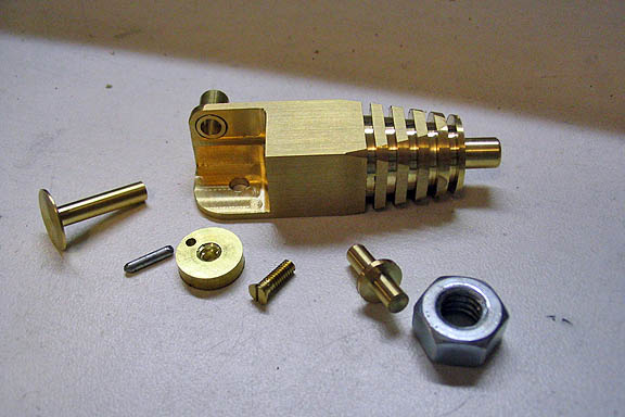
These are all the parts needed for the engine itself. The large piece is the
cylinder, and it has had the crank bearing pressed into it. The other parts, from
left to right are, the piston, crank pin, crank disc, crank disc screw, crankshaft,
and a standard 1/4" nut shown for scale.
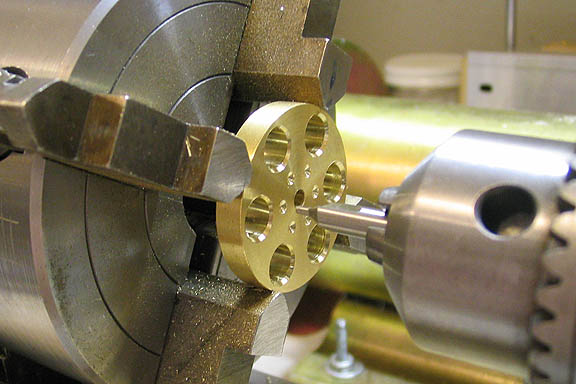
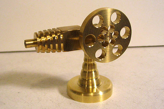
The flywheel is just a disc of brass 1 1/4" in diameter and 3/16" thick. It is cut
from brass stock and faced off on both sides. It needs to be chucked up accurately
so that the center hole can be drilled and reamed. After that is done, make whatever
hole pattern looks good to you. All the holes are just for decoration, so they can
even be left out if that's what you prefer.
When the flywheel is finished, the solid end of the crankshaft can be installed in
its center bore. It can be soldered in, or simply held in with Locktite, which is
probably the easier method.
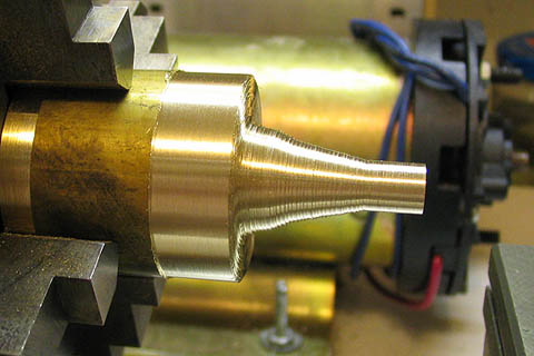
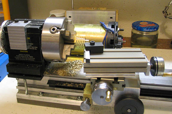
The base is another piece that can be made to suit your tastes. This
one has been roughed out by taking a number of progressively shallower
cuts along it's length to make a kind of funnel shape. Then files of
different shapes are used to finish it to the final contour.
Here's a Youtube link to this engine running:
To assemble the engine, press the crank bearing into the side hole in the cylinder.
Make it flush with the inside of the open part of the cylinder wall. If it's too loose
for a press fit, solder it. Locktite may work too.
Press the crank pin into the crank disc. Take care to make sure it goes in straight.
Put the piston on the crank pin and slide the piston into the cylinder bore with the
crank disc facing the bearing.
Slide the threaded end of the crankshaft into the bearing, then center the crank
disc over the bearing and screw in the 2-56 flat head screw.
Check to see that the flywheel turns easily and that there are not tight spots as
the piston goes in and out of the cylinder. If it's tight, it won't run. The most
likely reason for tight spots is that the crank pin is not quite straight in the crank
disc. Examine it carefully as you turn the flywheel. It's also possible that the
piston will rub on the cylinder walls as it rocks up an down. It may be that when
everything is put together, it will have to be disassembled for some fine
finishing of the piston, crank pin, or crankshaft.
Lubrication: I found that my engine runs best without it. If I use oil on the crank
pin and crankshaft, it takes a little more air to make it run. Without oil, it will
run on just a whisper of air, and it will run down to a slower speed before it stalls.
If you want to use oil, I'd suggest very light watch oil. 3 in 1 oil and other similar
products will really slow it down.
More Taig Lathe & Mill Projects
deansphotographica.com
(home page)
Copyright Dean Williams
Web Counters