Building the Bijou Engine
This is a small oscillating engine designed by Dr. James R. Senft. Dr. Senft did some work for NASA, and also did a
fair bit of R&D on the Low Temperature Differential engines, like the kind you can run off the heat of a coffee cup.
Dr. Senft called this engine Bijou. It's pretty small, though not the smallest he has demonstrated. One of his designs
is much smaller than the one I will be building here. (You could fit a number of his smallest design inside a sewing thimble.)
This project is very well suited for very small machine tools, given they are fairly accurate. I have a few different machines
in my shop, but I usually turn to my Taig lathe for anything that will fit on it. The work could be done on larger machines,
of course, as long as they can be held to close tolerances. The parts for this particular engine are quite small, and mistakes
and machine runout are magnified as parts decrease in size. I also used my Taig milling machine for the milling chores, but
a milling machine is not needed if you have a milling attachment for your lathe.
It's quite a fun engine to build, and as a bonus it is a stellar runner, and to top it off, the materials cost will be very low.
So, read on if you are interested in the build process, or go to the bottom of the page if you just would like to see it run.
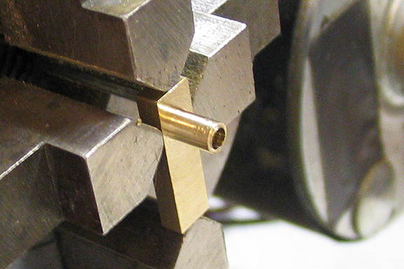
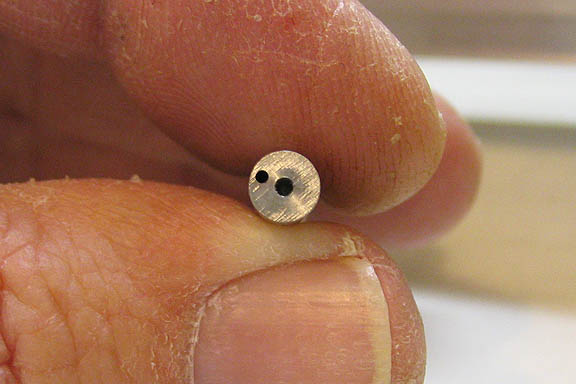
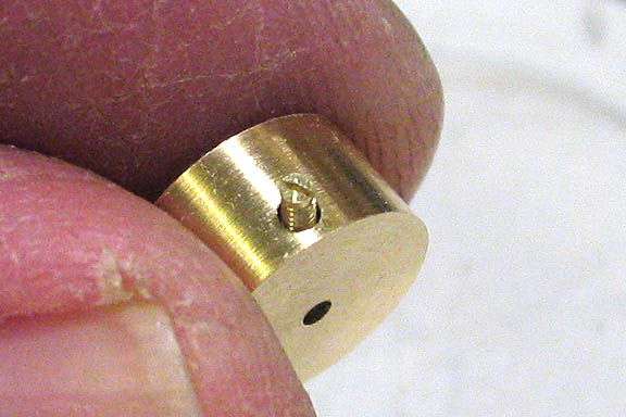
I started with the standard. This is the piece that all other pieces are mounted on. It also serves as the port face for
the cylinder. Here, the pivot bearing has been turned on a small piece of brass. The hole in the round bit is where the
pivot piece on the cylinder comes through. The hole diameter is .086".
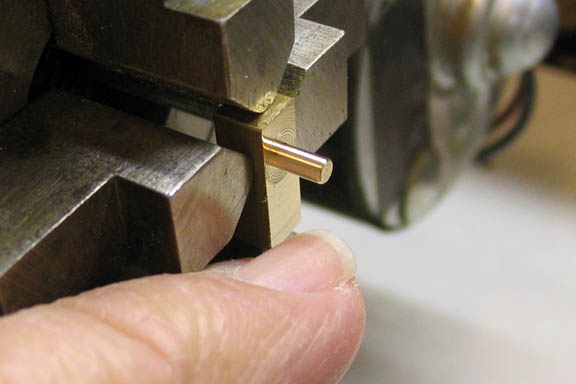
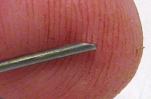
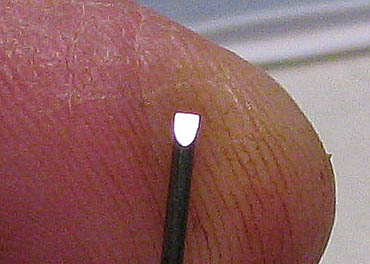
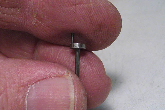
This is the cylinder, along with my little finger.
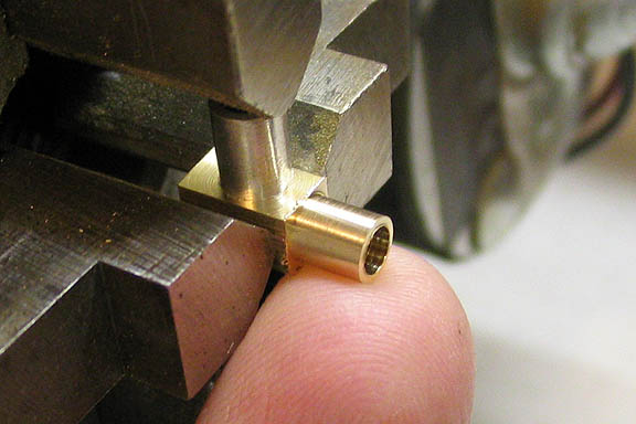
Here, the cylinder has been re-mounted in the four jaw for reaming the bore. The round bit under the upper chuck jaw
is a piece of tubing placed over the pivot shaft so the jaw does not damage it.
The cylinder is the "trunk guide" type. The trunk, the lower part where the piston goes in, acts as a cross head.
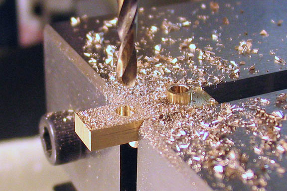
A little mill work on the standard. The drill bit is .093" diameter, making the hole needed for the main bearing,
which will be pressed into that hole later.
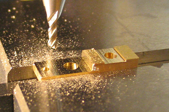
A 1/16" end mill is used to cut away all the un-needed metal.
Once the standard and cylinder were fairly well done, the piston was turned from stainless steel.
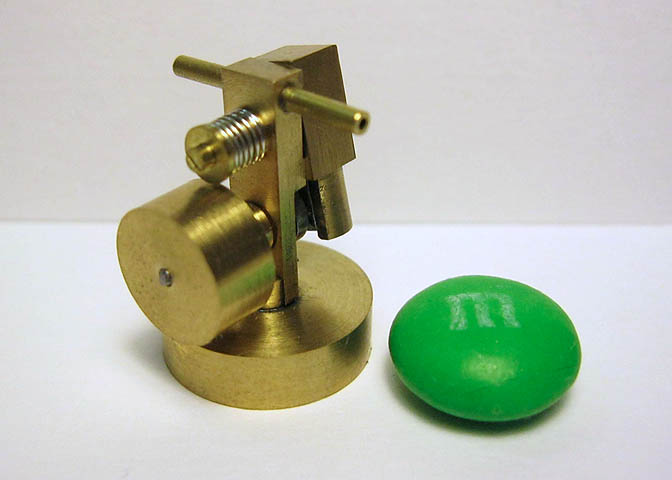
These are the pieces so far, next to your standard M&M candy. Piston, cylinder, and standard.
The ports will be drilled later, if I can find a small enough drill bit.
This is the cylinder, standard and piston assembly.
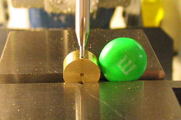
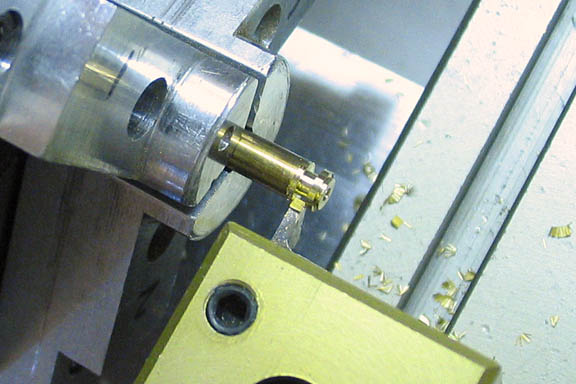
I set up for cutting the main bearing using some 660 bearing bronze. In the shot above the piece has been
roughed out and a center spot put in the end for drilling the bore. The bore was drilled a thou under size
to allow cleaning up with a reamer.
I don't have a store bought reamer in .047" (1.2mm), which is the size needed for the crankshaft bore, so I made up
a little shop reamer using hardened pivot wire. These are usually called "D" reamers, or D-bits. Normally,
for a larger size it would be made up from drill rod, the end machined to make the cutting edge, then hardened.
For this one I made it in a kind of half lozenge shape using an india stone to grind away the basic shape.
Then to finished it off and make it sharp, it is stoned on a hard white arkansas stone. I think it's called
slip stone in other parts of the world. Since it is already hardened to begin with, there is nothing more
to do to make it ready for use. Pivot steel is hard enough to cut brass, bronze and aluminum just the way it is.
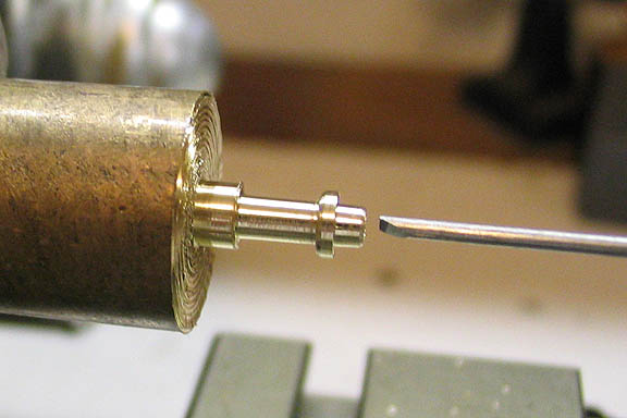
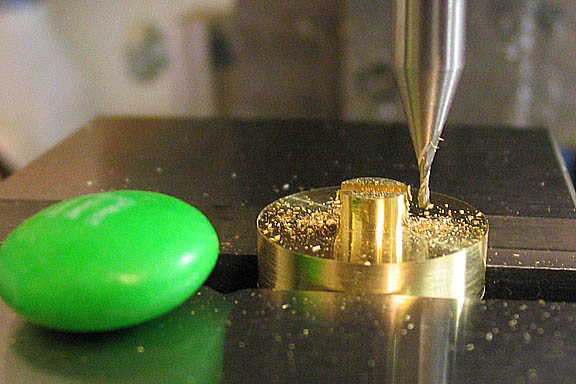
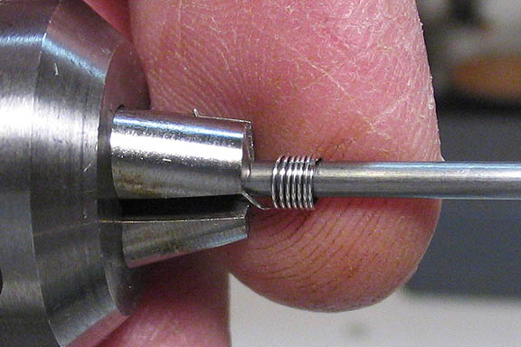
Now the reamer is run down the bore with the lathe running. Since this is a no clearance/no flute cutter, it can only
go in a tiny bit at a time, then has to be withdrawn to clear the tool and hole of shavings. Once the reamer
has cut the length of the bore, it's finished and the part can be cut off the parent stock.
Parts shot. The bearing, (front left) is a press fit in the engine standard.
To make sure the bearing goes in straight I cut and bored a small aluminum piece to back up the bearing against
the lathe chuck, then pressed on the standard using a brass rod to push against the standard with the tailstock.
Sorry for the fuzzy pic. It happens.
I wanted to check that the bearing was pressed in straight. If it's not, the engine won't run. I put a pivot wire
the same size as the crankshaft into the crank bore and put some more eyeball on it. It's good. I'm glad!
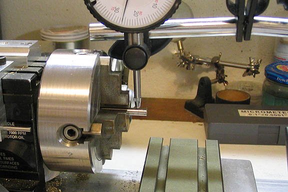
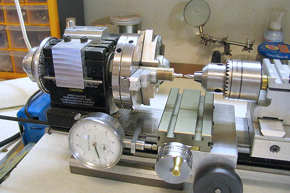
To setup for drilling the crank disc, a piece of steel rod is dialed in on the four jaw to show .125" runout. That
will give the crank pin offset of 1/16". Then the piece is drilled .031" for the pin. Next, the steel rod is
dialed in for no runout and an .047" hole popped down it's center, which will be for the crankshaft itself.
Here you can see the hole for the crankshaft, and the offset hole for the crank pin.
Once again, I used the tailstock on the lathe to press in the two shafts, and crankshaft is done.
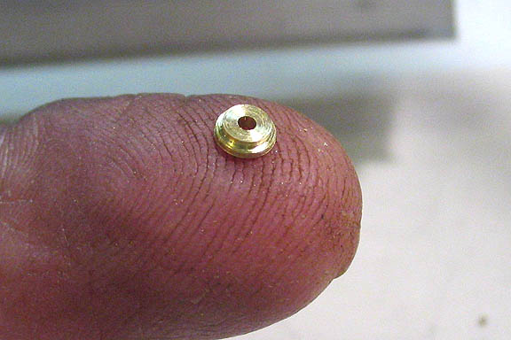
The flywheel is a simple turning and boring job, then it gets drilled and tapped for the 00-90 crank set screw.
I turned up a piece for the base, too. Here, it's having a slot milled with a 1/32" end mill.
Made a couple of little screws. The fasteners in this engine are 00-90. That's about 1.2mm for folks on the
sillimeter system. I don't like making very small screws so much. The failure rate on them is about 50%. They
tend to break off in the threading die, even with the die opened up all the way. I made five to get two good ones.
One goes in the flywheel to lock it on the crankshaft.
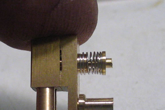
Made a little spring from steel guitar string. This spring keeps the cylinder pressed against the port face.
You can use any solid steel guitar string for making various size and strength of spring. They are music wire,
which is what commercial springs are made from.
This little thing is a washer made with two steps. One step larger than the OD of the spring and the smaller
step fits inside the spring.
You can see it better here. This is the second one I made. The first one rolled away at the moment it was
parted off. I had put a thin wire inside it while parting, but the last bit of brass caught on the wire that
was supposed to keep it from getting lost, and the wire flicked it away. Usually, putting a wire down the
center of something you are parting off will keep it from getting lost as it comes off the parent stock. This
time it backfired.
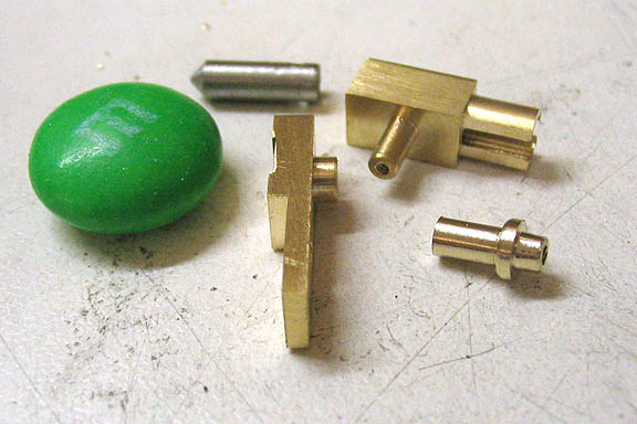
Here are the parts just made. Spring, washer, and screw.
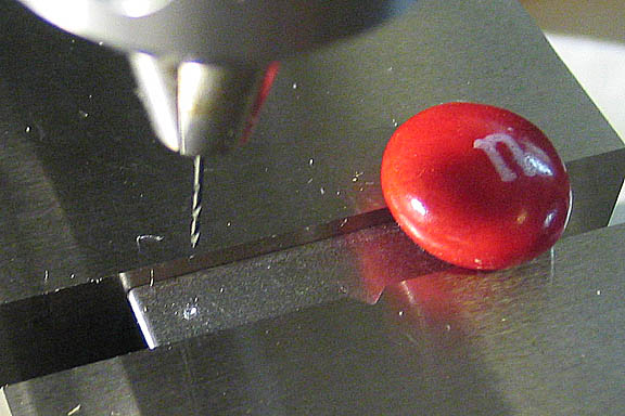
This piece will be a jig for drilling the port face holes, and the inlet hole in the cylinder. A .020" drill
is being use here, (1/2 mm). I'm doing this on the milling machine, as it has a very true spindle. The spindle on the
average drill press has too much runout to drill such a small hole, and the bit would be broken in a second.
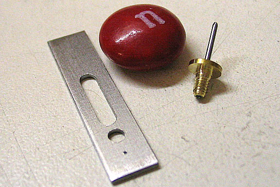
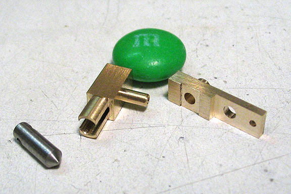
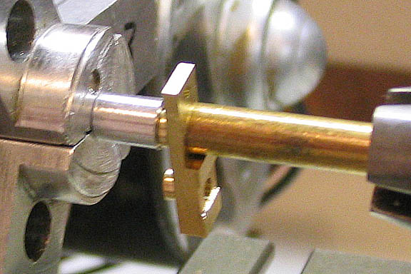
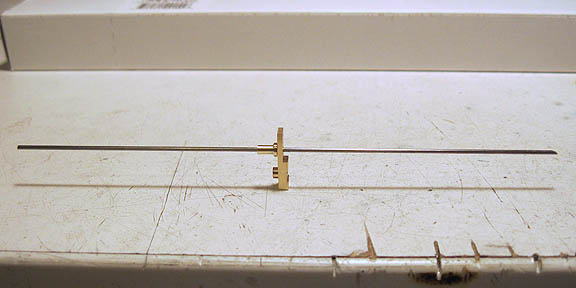
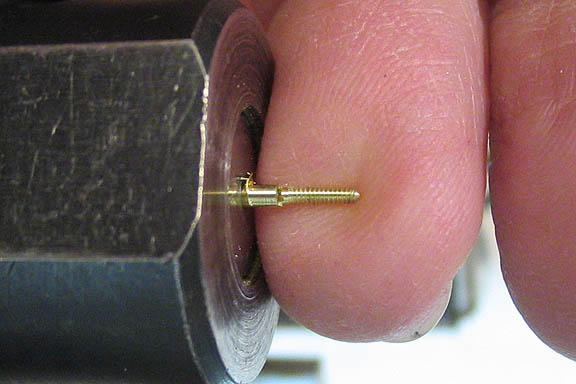
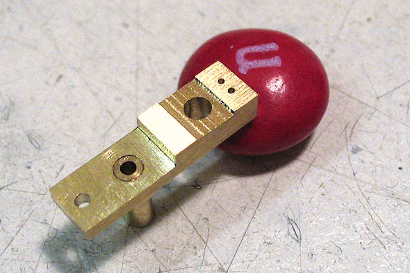
I also made up an alignment pin with a threaded end. These two jigs are used to accurately drill the ports
in the engine. The plate attaches to the crankshaft, and as the crank is rotated the plate will mimic the
arc traveled by the cylinder when the engine is running. The tiny hole will be used as a guide for drilling
the needed holes in the port face. The pin does the same thing for the hole that needs to go in the cylinder face.
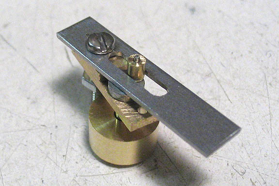
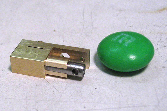
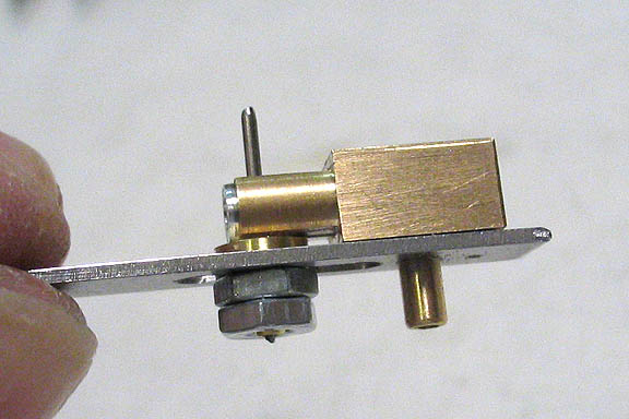
This is how the jig mounts to the port face of the engine. This may not be very interesting in itself, but
I wanted to show how one of these jigs works. A similarly made jig in larger scale will work perfectly for
aligning the steam ports for most any other oscillating engine.
If you were to need to fab a new port block for an engine, or say you soldered over the holes in an existing
port block, one of these can make your work in locating the holes not only easy, but very accurate.
What you need to know is the distance between the steam inlet in your cylinder and the pivot screw. Using a thin
piece of sheet steel, drill a hole in one end the same size as your port. Carefully measure from the center of
that hole and lay off the center of position for your pivot screw, and drill a hole the same size as that screw.
Finally, cut a slot in your jig piece. Take care to keep your two holes and the slot all in a straight line.
The length of the slot is not critical, as long as it allows you to mount the jig to your intended port face and
slip the slotted part over the crank pin on the crank shaft. Make the slot long enough to allow the flywheel/crank
to rotate through a full rotation. Also, make the slot just wide enough to let the crank pin enter it. It needs
to be a close fit.
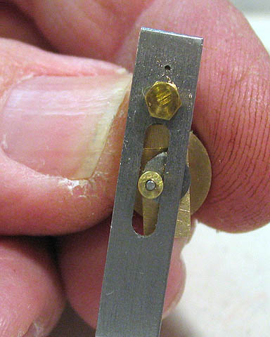
When you get ready to drill your holes in the port face, mount the jig to the face using the pivot screw for
the cylinder, or another screw of the same size. In the pic above, I've used a hex head screw through the jig
and through the pivot hole on the engine port block.
The slot is placed over the crank pin as shown above. I had to make a small bushing for this one, as the jig is
used for two different drilling operations. The bushing is needed to remove any slop between the pin and the slot.
Finally, the crankshaft is rotated, watching the jig travel through its arc. At the extreme points of the arc
on each side of the crank pin rotation, the top tiny hole is used as a guide for drilling the ports.
Hope that made some sense. Easier to do than to say/type.
This pic shows how well the jig works. Holes perfectly spaced.
I use this kind of jig for most all of my wobbler engine builds.
Just makes things easier, and gets it done in one go.
The same jig is used to put the single hole in the cylinder, but this time with an additional pin jig that
holds the cylinder bore perfectly in line with the crankshaft bore.
Two more holes are drilled in the port block, one for the inlet and one for the exhaust, then all the parts
can be assembled.
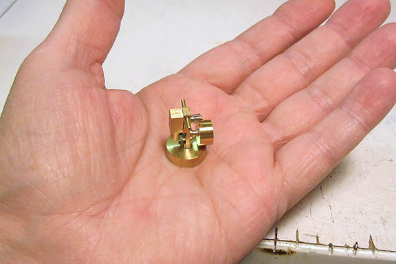
You can see how small the engine really is in this shot.
That's it, done.
Here's a video of it running on canned air. I've since made a fitting for it to run on a small boiler.
Runs on steam just like it runs on air. Video of that coming soon.
To go back to the main projects page, click the link below.
More Taig Lathe & Mill Projects
Copyright 1998-2010 Dean Williams